BOM-BOQ Tools
 Toolbar : BOM-BOQ Tools(CP)
Menu : CADPower -> BOM/BOQ Tools -> Create Bill of Materials/Quantities
 CmdLine : CP_BOM (or CP_BOQ)
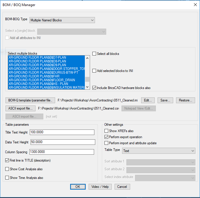
The CP_BOM tool is a Bill of Materials / Quantity take-off tool that also doubles up as an attribute extraction and CSV data import/export tool.
The CP_BOM tool support variious formats of quantity computation, like computing the quantity and cost based on the number of blocks (identified by names). You can also produce reports based on attribute values. You can produce quantities based on the number of times a particular attribute value occurs. You can compute and create a report of blocks based on the scale factors (area and volume calcculations).
The main BOM/BOQ computation starts with blocks as the primary input data. Blocks may or may not have attributes. It depends on the type of ouput required. All workflows and their parameters are defined in the main dialog and can be saved in INI files for easy restore. The format of the INI files is descibed below. Output from the CP_BOM tool is a table of text objects or a CAD Table entity and optionally exported into a CSV (or other delimited) file. The ASCII output format is easily imported into popular spread-sheets like Excel, Open Office etc.
The opertating parameters of the CP_BOM-Q command are stored in a paremeter INI file, which is a simple ASCII file. This file has several sections and they are described below under each relevant section
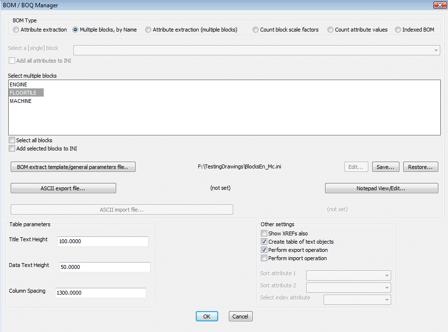
BOM Type:
Attribute extract: Single block name, multiple attributes extraction, tabulation, Excel CSV export/import (round-tripping possible)
This is an attribute extraction tool. Using this option, you select a single block name, extract its attributes to a CSV file, create a table of text in CAD and optionally, you can import the same table back from Excel after adding / deleting new data. During export of data into CSV, the handles of the blocks are exported as well. This enables the data to be updated into the attributes after import. Using this tool, you can export all attribute data to CSV, edit it in Excel and bring back the updated attribute data into CAD. A complete round-tripping of attribute data with dynamic update is possible.
[ATTRIBUTE_TAGS]
SHOP_NAME=Shop Description
AREA=Area (sq.m)
SHOP_NUMBER=Address
FLOOR=Floor Number
RENTAL_STATUS=Lease Status
[ATTRIBUTE_TAGS_END]
The attributes to be extracted must be specified in the INI file under the [ATTRIBUTE_TAGS] section as shown above. The values contained are the tag name and the attribute description (separated by =) as must appear in the table and CSV. If your block has many attributes, you do not need to create this section manually. You can select the attributed block from the pull-down and then select the Add ALL attributs to INI check-box.
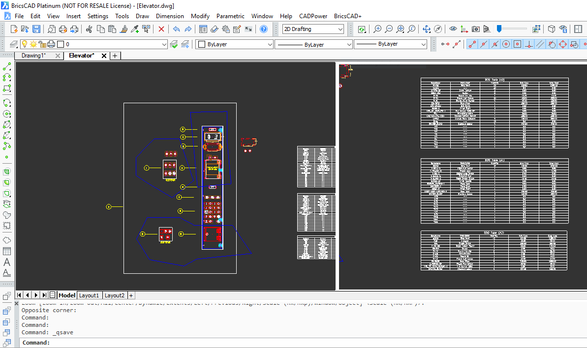
Attribute extract (per polygon): sam as the Attribute Extract option above but multiple BOQ tables are created based on selected polygon boundaries.
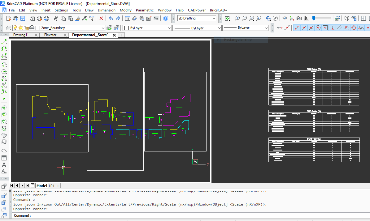
This is an attribute extraction tool on a per-polygon basis. You select multiple closed polylines and it will generate the table of attribute quantities within each closed polyline.
The rest of the options and workflow in this option is similr to the Attribute Extract option above.
You can use the CP_PARTASSIGN command to assign an name or ID to each one of the closed polyline. If such an ID is defined, it will be printed in the header of the table. This option can be used to generate an attribute quantitry table for a number of named polygons. For example, if you want to quantify the attribute values and count on a per-room basis, this option can be useful.
Multiple Named Blocks: Quantity and cost estimation of blocks by name. Creates table in CAD, exports CSV data. Accepts anonymous blocks also in the selection.
Using this option, multiple block names can be selected for processing and a table of block count can be generated. If there is a cost and time value associated with each block, it can be specified in the INI file and cost / time computation also be displayed in the table as well as the CSV file.
[BLOCK_NAMES]
BALOON_BLOCK=Standard baloon,50.0,2.5
BP-PLATE=Base Plate-generic,45.00,5.0
BP-SB=Base Plate Square,200.00,12.5
BP-SB1=Base platge Square Special,100.00,2.3
BP-SBAL=Base Plate Aluminium,24.00,8.5
BP-SBDC=Base Plate DC,80.00,12.8
BP-SBDO=Base Plate DO,130.00,45.8
CAPA3=Capcity Plate,45.00,1.5
CHICAGO-CYL=Chicago Cylinder,100.00,5.6
CHICAGO-CYL-FS04=Chicago Cylinder Special,200.00,4.5
CHICAGO-CYL-FS04_KEYSW=Chicago Cylinder FS,230.00,6.5
CUSTOM_AFF=AFF Block,150.00,7.8
Piston=Drive Piston,500.0,15.0
Crank Shaft=Sumi Drive Crank Shaft,100.0,8.0
Casing=Toshiba MC500 Casing,126.0,95.0
Bolts=25 mm bolts,30.0,15.0
[BLOCK_NAMES_END]
In the above example, the syntax is as follows:
<block_name>=<description>,<cost>,<time>
The multiple block names are specified in the INI files under the [BLOCK_NAMES] as shown above. If your drawing has many blocks, you do not need to create this section manually. You can select the blocks in the main dialog box and select the Add selected blocks to INI check-box.
The entries in the [BLOCK_NAMES] section need not be defined-in-the-drawing or physically inserted blocks. You can even include entries here which are components of a composite block (see below - info about composite assembly blocks).
Composite Assembly blocks: It is also possible to have advanced quantty computation based on assemblies of block. For example, if you have a block called ENGINE, which is made up of a number of component parts, which you would also like to include in the quantity, cost and time computation, you can specify the ENGINE as a composite block. In this case, you will need to specify the components of the ENGINE block.
An example of how the [COMPOSITE_BLOCK_NAMES] section would lool like is shown below:
[COMPOSITE_BLOCK_NAMES]
A=[A1=5],[A2=10],[A3=20]
B=[Screws=15],[Bolts=18],[Nuts=13],[Nails=14]
ENGINE=[Piston=4],[Crank Shaft=2],[Casing=1],[Bolts=28]
[COMPOSITE_BLOCK_NAMES_END]
This means that the ENGINE block assembly is made up of Piston (4 numbers), Crank Shaft (2 numbers), Casing (1 number) and Bolts (28 numbers).
Each one of these components is defined in the [BLOCK_NAMES] section above. You can see that the last 4 items represent the component of the composite block.
When the CP_BOQ tool sees an ENGINE block, it is recognized as a composite block and the quantities within them will be taken and computed. Please note that the composite blocks within the ENGINE block need only be described in the INI file and need not be physically defined or inserted in the drawing.
Multiple Named Blocks (per polygon): same as the Multiple Named Blocks option above but multiple BOQ tables are created based on selected polygon boundaries. Entities inside each selected polygon are grouped into one table each.
This is an block name counter tool based on a per-polygon basis. You select multiple closed polylines and it will generate the table of block count quantity within each closed polyline.
The rest of the options and workflow in this option is similar to the Multiple Named Block option above.
Attribute extract (multiple blks) : Multiple block names with common attributes extraction, tabulation, Excel CSV export/import (round-tripping possible)
This option is similar to the Attribute Extract, but supports multiple block names sharing the same attribute names. Everything else is similar to the Attribute Extract option.
Count block scale factors : This work-flow is based on the X & Y scale factors of a template 1 X 1 unit block. For example, if you want to cover a flat area with panels, tiles or patterns that are defined as scaled blocks, you can use the CP_TILEPLACE command to do so and then use this BOQ option to make a summary of the scale factors and dimensions.
Descriptions and costs for each size of block are to be defined and stored in INI files. The program computes the number of each size of scaled block and also computes the area of each pattern and the total area.
The scale factors of various blocks, their descriptions and cost are defined in INI file in the section named as under:
[SCALEFACTOR_DEF]
TILE_ATT,1x1,Unit Size-Demo,100.0
TILE_ATT,300 x 800,Full-Sized,1700.0
TILE_ATT,400 x 800,Full-Sized,1800.0
TILE_ATT,300 x 700,Custom-Large,1800.0
TILE_ATT,300 x 50,Custom-Tiny,700.0
TILE_ATT,300 x 150,Custom-Small,600.0
TILE_ATT,300 x 300,Custom-SmallX1,650.0
TILE_ATT,300 x 300,Custom-SmallX2,700.0
TILE_ATT,300 x 450,Custom-SmallX3,600.0
TILE_ATT,300 x 200,Custom-SmallX5,550.0
TILE_ATT,300 x 250,Custom-SmallX6,750.0
TILE_ATT,300 x 550,Custom-MediumX4,1200.0
TILE_ATT,300 x 650,Custom-LargeX2,1850.0
TILE_ATT,300 x 500,Custom-MediumX2,1400.0
TILE_ATT,300 x 750,Custom-LargeX2,1800.0
TILE_ATT,300 x 400,Custom-MediumX3,1200.0
TILE_ATT,300 x 600,Custom-MediumX4,1300.0
[SCALEFACTOR_DEF_END]
In the example above, TILE_ATT is the name of the block, followed by its size, Description and Cost. Note carefully that all parameters are separated by a comma.
Another section of the INI file is the [SCALEFACTOR_RECORD] which defines the order of entries in the table as well as the CSV export. The key item names are shown as #Desc, #BlockName, #UnitCost, #TotalCost, #Size, #Quantity, #UnitArea and #TotalArea which must be specifed exactly as shown but in any order or combination as desired.
[SCALEFACTOR_RECORD]
RECORD_STRUCTURE=#Desc,#BlockName,#UnitCost,#TotalCost,#Size,#Quantity,#UnitArea,#TotalArea
LENGTH_UNIT_FACTOR=1.0
LENGTH_UNIT=mm
AREA_UNIT=sq.m
COST_UNIT=INR
[SCALEFACTOR_RECORD_END]
There are additional parameters like LENGTH_UNIT_FACTOR which you can specify to report the output in a unit that is different from the drawing unit. For example, the drawing unit may be mm and the panels may be sized and scaled in mm but the final area calculations need to be in sq.m or sq.ft. To handle such situations, this parameter helps.
Defining additional material resources
There is another section in the INI file that can be defined and it is called [RESOURCE&MATERIALS_DEFINITION]. This is a section where you can define cost/unit length, weight/unit length and time/unit length, and the same can be applied to linear objects quantity, time and cost calculation. Please be aware that this section strictly defines these parameters on a per unit length basis and not per block. If you want cost and time per block, it must be defined in the [BLOCK_NAMES] section anto not here.
[RESOURCE&MATERIALS_DEFINITION]
Cement=0.1,5.0,3.0
Glue=0.05,2.0,0.0
[RESOURCE&MATERIALS_DEFINITION_END]
For example, the above section defines the additional material resources that are added to linear objects in linear quantities computation. Example: Cement and Glue that is used to place a tile is defined here. The syntax is:
<Material_Name>=<Cost/unit length>,<Weight/unit length>,<time/unit length>
The above section is used in the computation of quantities using the CP_TILEPLACE or the CP_LINEQTY commands of the BOM-Q tools.
Count Attribute Values : Allows a bill of quantities to be generated based on the number of times a specific attribute value occurs. Attribute values can be linked to a description and cost which are specified in the INI file.
[ATTRIBUTE_VALUES_AND_COST]
W1=Window Type 1, 100.0
W2=Window Type 2, 125.0
V1=Ventilator Type 1,75.0
W4=Window Type 4, 50.0
FW1=Front Window Type 1, 120.0
W3=Window Type 3, 300.0
W10=Window Type 10, 3000.0
[ATTRIBUTE_VALUES_AND_COST_END]
The ATTRIBUTE_VALUES_AND_COST of the INI file contains all the info that is necessary to define the various attribute values and their cost. In the example shown above, you can see vraious window and ventilator types along with their cost information.
IndexedBOM: method allows to aggregate, count and report drawing data which are labeled using balloon blocks. A balloon block is a symbol (block with an attribute) created to represent a single part or cluster assembly in the drawing (the references are named A, B, C.... 1, 2, 3.... and so on). For each of these indexes, a description can be specified in the INI file and data can be presented in tabular form.
An example of data in the INI file is shown below
[INDEX_OF_ENTRIES]
1=Description of first entry
2=Description of second entry
A=Description of another entry
[INDEX_OF_ENTRIES_END]
For Indexed BOM, you need to have a block called BALOON_BLOCK which has an index attribute. The name of the index attribute is specified in the Select index attribute pull-down menu. A sample of such a block named BALOON_BLOCK is shipped along with CADPower and is found in the SUPPORT/BOM under the installation folder. The index attribute is called INDEX.
PartNames Count: This method will link directly to the CP_PARTCOUNT command of CADPower. This is work in progress and yet to be implemented.
Import Table Only: This method allows to simply import a CSV file from the disk and create a CAD tavle out of it. It does not create any BOM-Q.
Dynamic Blocks: A new option called 'Dynamic Blocks' has been added. Selecting this option allows you to select dynamic blocks which can be tabulated and counted as per their 'Visibility' states.
General parameters in INI file
[GENERAL_PARAMETERS]
EXPORT_FILE=F:\BricsCAD_Collaterals\BricsCAD_Demo_DWGs\2d_drawings_for_BOM\Space_Planning.csv
IMPORT_FILE=F:\Bricscad_Collaterals\BricsCAD_Demo_DWGs\2d_drawings_for_BOM\Space_Planning.csv
SCALE_FACTOR_FOR_TABLE=400.000000
BOM_TYPE=ScaleFactor
COLUMN_SPACING=1300.000000
TITLE_TEXT_HEIGHT=100.000000
DATA_TEXT_HEIGHT=50.000000
BLOCK_NAME=POLE
CREATE_TEXT_TABLE=Yes
EXPORT=Yes
IMPORT=No
BLOCK_NAMES_MULTIPLE=TILE_ATT2
INSERTION_POINT_OF_TABLE=2094464.272974,787664.229658,0.000000
KEY_ATTRIBUTE1=
KEY_ATTRIBUTE2=
INDEX_ATTRIBUTE=
DELIMITER_BETWEEN_TOKENS=,
[GENERAL_PARAMETERS_END]
The information contained under the [GENERAL_PARAMETERS] section above is where the general operating parameters of the CP_BOM command is stored, as described above.
Watch: ![]()
![]()
![]()
![]()
![]()
Toolbar : BOM-BOQ Tools(CP) 
Menu : CADPower -> BOM-BOQ Tools -> Place Tiles / XY Panels
CmdLine : CP_TILEPLACE
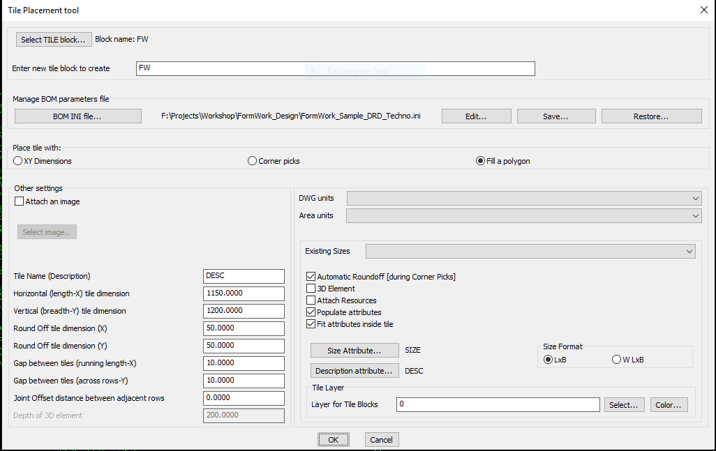
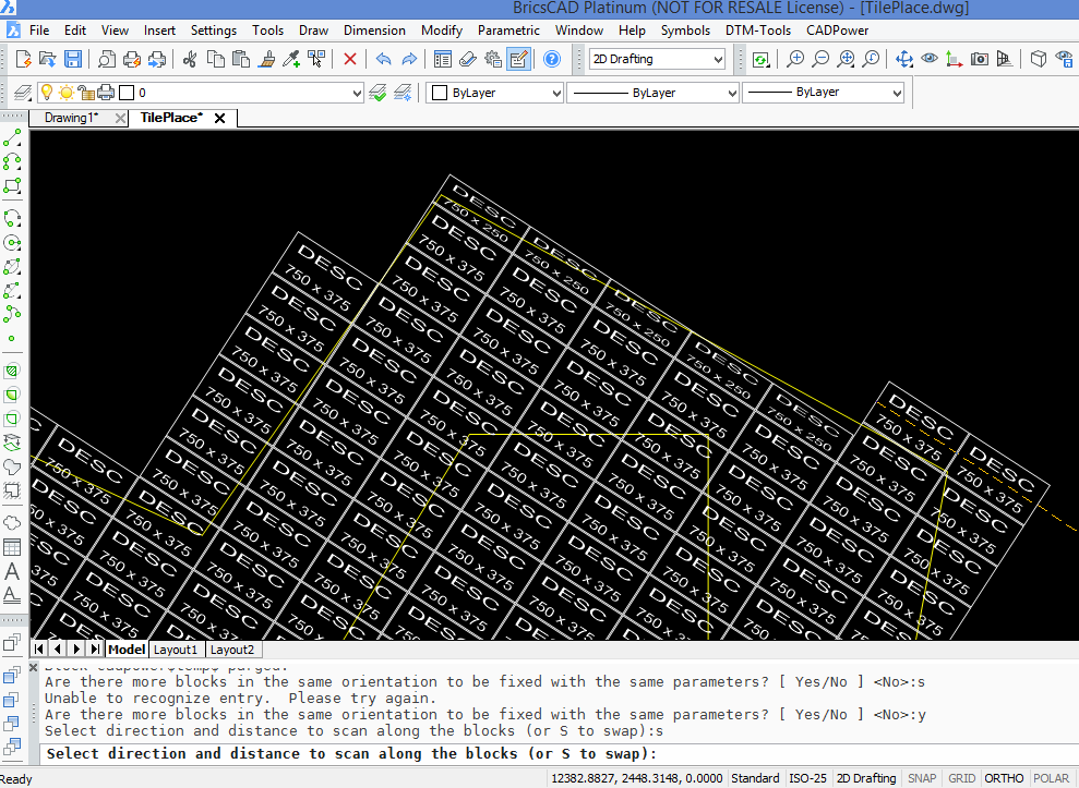
This is a space planning / filling tool. The CP_TILEPLACE command fills a closed polygon with a block which will be inserted to a specified scale of 'Length' X 'Breadth'. Useful for architects, engineers and anyone who wants to place rectangular panels or tiles which are cut to standard & custom sizes.
There are other options to place the rectangular block as well. You can just pick two corners by free-hand pick and let the command place automatically sized blocks which can also be rounded off to the specified value as entered in this dialog box.
Lastly, there is also the option to exactly enter the 'Length' and 'Breadth' value you required and you can place an exactly sized block at the desired location.
CP_TILEPLACE command requires a unit-sized ( 1 x 1 ) block to be defined with optional attributes for size and description. There can be any number of CAD entities within the 1x1 sized block. You are then asked to select a closed polygon (polyline, spline, ellipse or circle), and specify a 'standard' size for your panel, which will be placed and fitted in rows and columns across the area. These blocks will be scaled with the specified X and Y scales representing Breadth and Length respectively. When there is not enough space at the ends, near the polygon boundary, a smaller filler block will be used. The filler block has the same Breadth as the standard block. The length will be adjusted as per available space. It is possible to specify a rounding off dimension as well as gap distances along the panels and across the panels. There is also an option to fill the polygon with an image.
It is also possible to attach an image (JPG etc.) within the block. The image should be ideally square in size and represent a material pattern or poster or such feature. Selecting an image which is not a square will result in the image being scaled in X and Y dimensions. Using the image fill option, it is possible to closely match the SUPERHATCH functionality that is available in the Express Tools. To add an image in your panel, please check the option called Attach an image.
The CP_TILEPLACE command now automatically detects and processes island polygons within the main one. And the panels are placed accordingly.
The CP_TILEPLACE command works closely with the CP_BOM command. The parameters for this command are defined in the INI file which is used by the CP_BOM command. This command creates scaled tile blocks which are used by the 'Count block scale factors' workflow of the CP_BOM command.
The CP_TILEPLACE command finds great use with fabrication engineers, construction form-work designers and similar kinds of processes.
After the initial block has been placed, you can also use the CP_SCLEDIT command to interactively edit and change the X and Y scale factors of the block interactively and dynamically.
Other settings:
Attach an image: Checking this option allows to attach an image in your tile block. The image will be scaled and applied across the area that needs to be covered.
It must be a raster image and ideally should be square in size, to minimize distortions and unexpected scaling.
Horizontal (length) tile dimension: This is the standard length of the tile in X direction. When the unit block is placed with a rotation of 0.0, the X scale factor is considered as the horizontal or length dimension.
Vertical (height) tile dimension: This is the standard length of the tile in Y direction. When the unit block is placed with a rotation of 0.0, the Y scale factor is considered as the vertical or height dimension.
Round off tile dimension: Any standard tile at the ends which don't fit is rounded off in the X direction to the value specified here. If you have 300X800 as the standrad size and 50 as the round-off dimension, the edge pieces are created as 300x750, 300x700 and so on.
Gap between tiles (running length): This is the gap that must be left between the two tiles in the direction in which it is placed.
Gap between tiles (across rows): This is the gap between two tiles between adjacent rows.
Joint offset distance (across rows): This is the offset distance between the tile gaps in adjacent rows. By default, this is set as 0 which means there is no overlap between the joints in adjacent rows. It is often required to have the joints staggered in between in the middle between each row. In such a case, the joint offset must be entered as as half of the length dimension.
General tips: A little bit of trial and error is necessary to understand how the program places the rows and columns of panel blocks. Once you understand the functioning of this tool, it is quite a powerful tool in being able to perform a lot of your presentation and quantity computation tasks.
Watch: ![]()
![]()
Toolbar : BOM-BOQ Tools(CP)
Menu : CADPower -> BOM-BOQ Tools -> Offset Tiles / XY sized panels
CmdLine : CP_TILEOFFSET
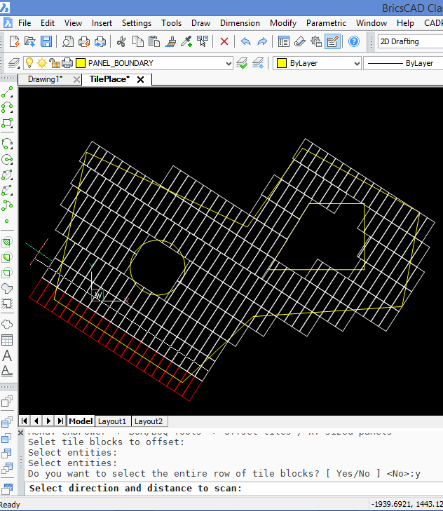
The CP_TILEOFFSET command is used to offset a single tile or an entire row of tiles along the direction of their placement. The panels can be placed placed manually or using the CP_TILEPLACE command. Selecting one single panel gives the user the option to automatically scan and select the entire row of panels at once. The direction of the row which will be offset is identified by the rubber-band drag line which connects the middle of one of the segments of the tile and the other end as indicated by the setting of the ORTHO mode.
Toolbar : BOM-BOQ Tools(CP)
Menu : CADPower -> BOM/BOQ Tools -> Create Bill of Materials/Quantities
CmdLine : CP_TILECOUNT
The CP_TILECOUNT command runs the CP_BOM tool and is provided for convenience and visibility. The CP_BOM tool supports a workflow that counts the block scale factors. All block scale factors that are likely to be used in the drawing must be defined in the INI file.
Toolbar : BOM-BOQ Tools(CP)
Menu : CADPower -> BOM-BOQ Tools -> Edit Tiles / XY panels
CmdLine : CP_TILEEDIT
The CP_TILEEDIT command is an interative editor for X & Y scale factors of panel blocks. If you have a row of XY panel blocks and want to edit the X or Y scale factor of all blocks together, you can use this command. This tool is useful to trim the blocks at the boundaries of the area where you are placing the panels.
Using CP_TILEEDIT, you first edit one block and specify the desired X and Y scale factors. You can also set the anchor point around which the scaling must happen. Based on this, you select all the other blocks in the row (or column) and the command automatically applies the same editing operation on all the blocks.
Toolbar : BOM-BOQ Tools(CP) ![]()
Menu : CADPower -> Blocks -> Block-related -> Interactive XY Scale Editor
CmdLine : CP_SCLEDIT
Description Pending
Watch: ![]()
Toolbar : BOM-BOQ Tools(CP) 
Menu : CADPower -> BOM-BOQ Tools -> Draw Developed Walls from plan footprint
CmdLine : CP_BUILDWALLS
The CP_BUILDWALLS command is used to draw a developed elevation view of a set of connected walls from its plan footprint. The walls are all represented as closed rectangular polylines and numbered sequentially from 1, and placed in an appropriate layer determined by the floor number.
Toolbar : BOM-BOQ Tools(CP) 
Menu : CADPower -> BOM-BOQ Tools -> Set Height & Length of wall segments
CmdLine : CP_SEGLENHGTSET
The CP_SEGLENHGTSET command is used to set the heights of individual walls in a room. The room footprint is represented by a closed polyline and each wall is a segment of the polyline.
Toolbar : BOM-BOQ Tools(CP) 
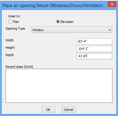
Menu : CADPower -> BOM-BOQ Tools -> Place Openings
CmdLine : CP_PLACEFIXTURES
CADPower defines two blocks for openings: SP_OPENINGS_ELEV and SP_OPENINGS_PLAN. This is a simple rectangular block that has the following attributes: SILL_HEIGHT, WIDTH, HEIGHT, DEPTH (for recesses) & TYPE.
Toolbar : BOM-BOQ Tools(CP) 
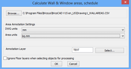
Menu : CADPower -> BOM-BOQ Tools -> Compute Wall/Openings areas
CmdLine : CP_COMPUTEWALLAREAS
The CP_COMPUTEWALLAREAS command takes wall elevations and the window/door/openings and computes a schedule of fixtures, their areas as well as the net area of walls.
Toolbar : BOM-BOQ Tools(CP) 
Menu : CADPower -> BOM-BOQ Tools -> Compute linear quantities
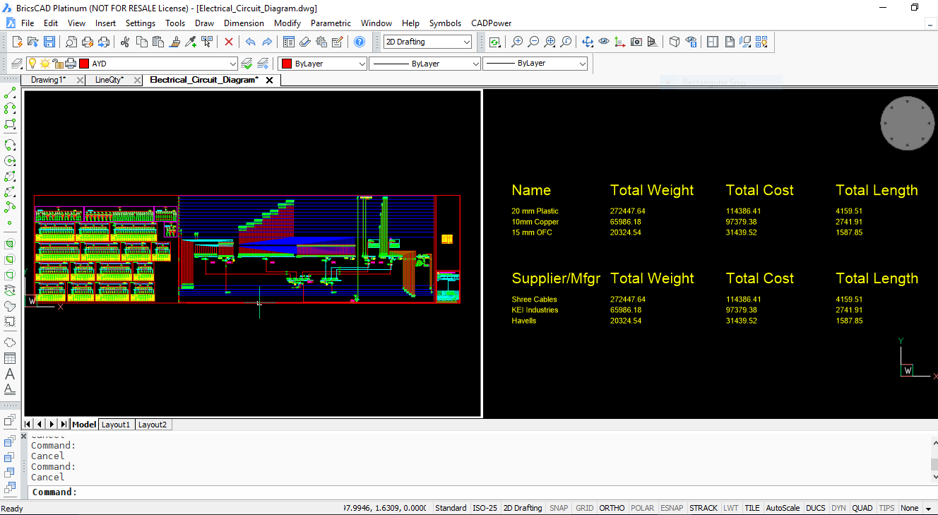
CmdLine : CP_LINEQTY

The CP_LINEQTY command creates a summary of linear quantites by computing length of selected objects and using wieght/unit lengh and cost/unit length as primary input parameters. All data required is attached as DATA to the linear entities. The XDATA is attached to the entities using the CP_DATAMAN command and its structure defined in an INI file.
The INI file must have a minimum of 3 fields. 'Name', 'Cost per Unit length' & 'Weight per unit length' in exactly the same order. A fourth suggested field is 'Supplier' or similar but is not mandatory. Additionally custom XDATA fields can be added but it ignored by the CP_LINEQTY command. The output of CP_LINEQTY is the cost, weight and length calculations in table form based on 'Name' (the first field) and optionally 'Supplier' (the fourth field).
A sample structure of the INI file for computing length and weight/cost of reinforcement bars looks like this. Explanation about the syntax is provided after each section.
[*RECORD] Name=LINE_INFO
Type=XDATA
FIELD=Name,String,Linear Part
FIELD=Weight per unit length,Real,1000.0
FIELD=Cost per unit length,Real,500.0
FIELD=Supplier,String,Linear Part Manufacturer
[*RECORD_END]
>> The name of the record is LINE_INFO, It can be used to describe your linear element, which can be a rebar, pipe, cable, duct or casing etc.
>> The Type field is XDATA. Leave it as it is. It means that data is attached to entities as XDATA
>> The first 3 fields of the INI file are mandatory. The first field (in this example, 'Name') is used to identify the linear element and can have any name.
>> The second field 'Weight per unit length' must be as it is and defines the weight per unit drawing length
>> The third field 'Cost per unit length' must be as it is and defines the weight per unit drawing length
>> The fourth parameter is optional and, if present, will be used to compute a table of quantities based on this parameter.
>> The fifth parameter is also optional and, if present, will be used to compute a table of quantities based on this parameter.
[*FIELD_VALUES]
Name=Name
Values=Type 1
Values=Type 2
Values=Type 3
[*FIELD_VALUES_END]
>> These are the different pre-defined values of the first parameter (in this case, it is called 'Name')
[*FIELD_VALUES]
Name=Weight per unit length
Values=100.0
Values=200.0
Values=300.0
[*FIELD_VALUES_END]
>> These are the different pre-defined values of the second parameter (called 'Weight per unit length)
[*FIELD_VALUES]
Name=Cost per unit length
Values=1000.0
Values=2000.0
Values=3000.0
[*FIELD_VALUES_END]
>> These are the different pre-defined values of the third parameter (called 'Cost per unit length)
[*FIELD_VALUES]
Name=Supplier
Values=Company 1
Values=Company 2
Values=Company 3
[*FIELD_VALUES_END]
>> These are the different pre-defined values of the fourth (optional) parameter (called 'Supplier')
[*SIZE_VALUES]
Name=Size
Values=Size 1
Values=Size 2
Values=Size 3
[*SIZE_VALUES_END]
>> These are the different pre-defined values of the fifth (optional) parameter (called 'Size') You need to first attach data to linear entities like CIRCLE, LINE, ARC, POLYLINE, LWPOLYLINE or SPLINE objects. This is done using the CP_DATAMAN command using the same INI file as above.
Once the data is attached, you can derive the linear quantities using the CP_LINEQTY command.
A sample INI file to define the above data structure in included in the installation. It is available in the SUPPORT folder under CADPower installation.
Watch: ![]()
Toolbar : BOM-BOQ Tools(CP) ![]()
Menu : CADPower -> BOM/BOQ Tools -> Estimate reinforment quantities
CmdLine : CP_BARMAN
Description Pending
Toolbar : BOM-BOQ Tools(CP) ![]()
Menu : CADPower -> BOM/BOQ Tools -> ERP Export Tools -> Convert text table to Excel CSV data
CmdLine : CP_CONVERT2EXCEL
Description Pending
Toolbar : BOM-BOQ Tools(CP) 
Menu : CADPower -> BOM-BOQ Tools -> Parts Management -> Assign part names
CmdLine : CP_PARTASSIGN
The CP_PARTASSIGN command assigns a part name to selected objects. This is a simple data assignment tool that attaches a string (we call it Part Name) to one or more objects. When you have a drawing with multiple objects tagged with part names, it is used to create part labels, count them and present in a simple table of part names versus number of times it occurs. This forms the basis of a simple quantity
table.
Watch: ![]()
![]()
Toolbar : BOM-BOQ Tools(CP) 
Menu : CADPower -> BOM-BOQ Tools -> Parts Management -> Un- Assign part names
CmdLine : CP_PARTUNASSIGN
The CP_PARTUNASSIGN command removes part names attached to objects by the CP_PARTASSIGN command.
Watch: ![]()
Toolbar : BOM-BOQ Tools(CP) 
Menu : CADPower -> BOM-BOQ Tools -> Parts Management -> Label part names
CmdLine : CP_PARTLABEL
The CP_PARTLABEL command creates a text label that represent the part name attached to selected objects. It is created at the centroidal location of the object with a user-defined text height.
Watch: ![]()
![]()
Toolbar : BOM-BOQ Tools(CP) 
Menu : CADPower -> BOM-BOQ Tools -> Parts Management -> Count part names
CmdLine : CP_PARTCOUNT
The CP_PARTCOUNT command summarizes the occurences of part names attached to selected objects and writes them down in a simple 2-column table. The same is exported to a CSV file to further action in Excel.
Watch: ![]()
![]()
Toolbar : BOM-BOQ Tools(CP) 
Menu : CADPower -> BOM/BOQ Tools -> Panels, Layout & Sizing -> Cut a rectangular sheet with gap allowance
CmdLine : CP_SHEETCUTTER
Recently, we met a few CAD users whose job is to lay polymer sheet cuts and create lining for the insides of hoppers and silos. These kinds of companies start with a rectangular standard sheet and cut pieces are generated out of it such that wastage is minimal. Optimization is the key.
The first tool in this series has been created under a new sub-heading called 'Panels, Layouts & Sizing' under the BOM/BOQ tools.
The CP_SHEETCUTTER command takes a closed, rectangular polyline and cuts it into two parts as per required measurement. The cut is made across the rectangle with a specified gap for the cutting tool. The end result are two closed polylines meeting the design requirements. There is an option to enforce a symmetric or non-symmetric cut with precise positioning.
Watch: ![]()
Toolbar : BOM-BOQ Tools(CP) 
Menu : CADPower -> BOM/BOQ Tools -> Panels, Layout & Sizing -> Cut an artibrary shaped sheet with gap allowance
CmdLine : CP_SHEETCUTTERARBITRARY
.
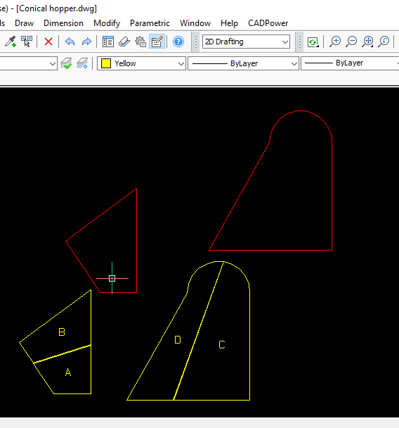
The second tool in this section extends the functionality of the first one, the CP_SHEETCUTTERARBITRARY command allows to split a multi-sided irregular polygon into two pieces with a specifed gap in between. Automatic part numbering of the two ieces are also automatically done.
Watch: ![]()
Toolbar : BOM-BOQ Tools(CP) 
Menu : CADPower -> BOM-BOQ Tools -> Parts Management -> Cut a linear item into pieces
CmdLine : CP_PIECEMAKER
The CP_PIECEMAKER command is used to create a quantity schedule of smaller cut pieces from a larger un-cut length. This can be useful for scheduling of linear elements like reinforcement, pipes, wires, cables etc.
There are a number of inputs you must provide as shown below:
The CP_PIECEMAKER command is used to schedule your cuts efficiently. Starting with a full un-cut piece of linear element, you can now easily create a quantity schedule of cut pieces. The gap allowance also needs to be specified (optional) and the quantity schedule of cut lengths and their quantities are displayed in a CAD table as well as exported to Excel-ready CSV files.
A pictorial true-to-scale representation of the cut pieces is also generated in the drawing.
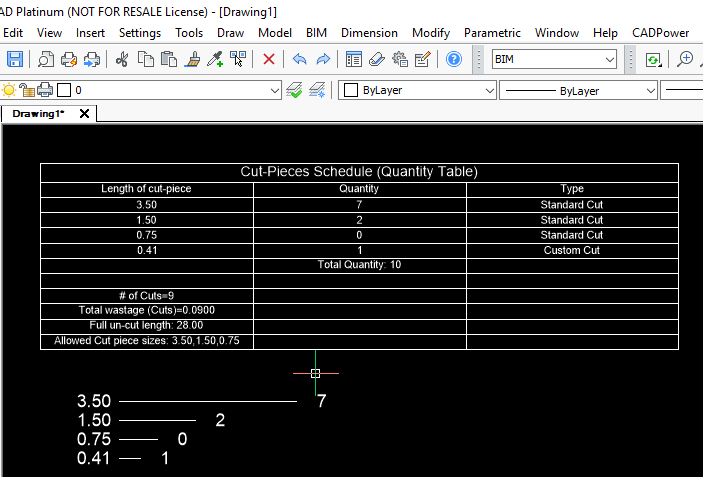
Output created as a CAD table in BricsCAD
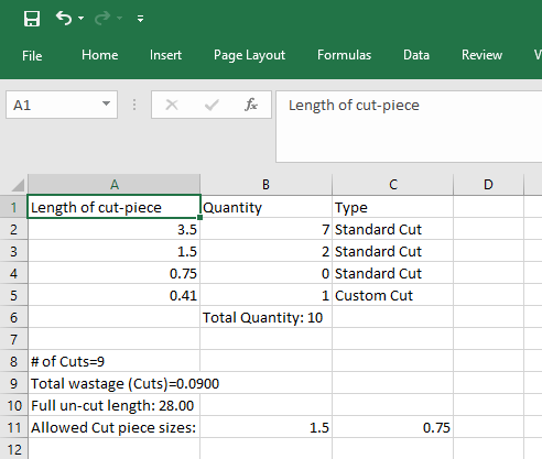
Output exported to Excel via CSV files
Watch: ![]()
![]()
Toolbar : BOM-BOQ Tools(CP) 
Menu : CADPower -> BOM/BOQ Tools -> Panels, Layout & Sizing -> Slide a polygon and create adjacent copy
CmdLine : CP_POLYSLIDE
The CP_POLYSLIDE command is created to precisely position tapered cut pieces that fit along the slope of a larger polygon. The CP_POLYSLIDE command requires that you first start with a geometry that is a polygon with two parallel sides. For example, if you have arrived at a trapezoidal shape that needs to be fitted within a polygon, and require that the shape be placed adjacent to each other with a specified gap, this is the right tool to use.
The CP_POLYSLIDE command asks for the first slide point, second slide point and a third adjacent side point. The polygon then slides in that direction, applies a gap and places the next piece in the way that makes sense for sheet placement.
Toolbar : BOM-BOQ Tools(CP) 
Menu : CADPower -> BOM-BOQ Tools -> Parts Management -> Dynamic and precise polygon editing
CmdLine : CP_MVEDIT
We have had the CP_MVEDIT tool for many years. It had had a complete makeover now and can be used for polygon sizing.
There are two new options added in ths command - 'Move Dynamic [General]' and 'Move Dynamic [Custom]'. These two options allow you to select polyline vertices and move them dynamically in specified intervals until you are satisfied with the result.
The first option 'Move Dynamic [General]' allows moving the seleted vertices in any one of the direction X, Y, Z, XY, YZ, XZ and XYZ by specified increments. You can control the movements on the command line until you are satisfied with the result. There is also a 'Reverse' option that allows you to reverse the trend and move in the opposite direction of the selected axes.
The second option 'Move Dynamic [Custom]' allows precise movements of two (and only two) selected vertices in pre-defined directions like:
'TowardsEachOther'
'AwayFromEachOther'
'First2Second'
'Second2First'
With these options, you will be able to precisely position vertices based on measured, interactive movements.
Going forward, we will be adding more innovate ways to position the selected point. I request feedback from our users what they would like to see in this tool. We have created this tool for the panel sizing and layout process, but I foresee this as a generic requirement that almost any CAD user may have from time to time. The context and application are going to be different but the necessity is universal.
Watch: ![]()