Build Tools
 Toolbar : Build Tools
 ![]()
Menu : CADPower -> Build -> Offset -> Multiple-Offset relative/absolute CmdLine : CP_MOFFSET
The CP_MOFFSET command is used to offset the selected object multiple number of times. In Relative mode, the offset distances are calculated relative to the last object that was offset.
Toolbar : Build Tools 
Menu : CADPower -> Build -> Offset -> Multiple Offset - Absolute CmdLine : CP_MOFFSETA
The CP_MOFFSETA command is used to offset the selected object multiple number of times. In Absolute mode, the OFFSET distances are calculated from the first object that was chosen for offset.
Toolbar : Build Tools 
Menu : CADPower -> Build -> Offset -> Offset and delete original CmdLine : CP_OFFSET
The CP_OFFSET command is used to offset an object and delete the original object. This is a quick way to displace an object sideways. Use this command when you wish to save yourself the bother of deleting the original object.
Toolbar : Build Tools 
Menu : CADPower -> Build -> Offset -> Offset 3D polylines CmdLine : CP_3DOFFSET
The CP_3DOFFSET command is used to offset 3d polylines in the same manner as 2d polylines. 3D polyline can be offset both horizontally and vertically. This can be a very useful in several civil engineering design situations that require the offsetted polyline to be elevated or lowered by a fixed amount relative to the source polyline.
Toolbar : Build Tools 
Menu : CADPower -> Build -> Offset -> Offset single segment of polyline CmdLine : CP_SEGOFFSET
The CP_SEGOFFSET command is useful to offset a single segment from a polyline. You will be asked to pick the segment and it will be offset using the standard OFFSET command.
Note: If you pick a segment which contains arc segments, the offsetting segment will be the straight line joining the two points and not the arc. Fitted and Splined polylines cannot be used by this command.
Toolbar : Build Tools 
Menu : CADPower -> Build -> Offset -> Multiple variable polyline segment offset CmdLine : CP_MVOFFSET
The CP_MVOFFSET command allows individual polyline segments to be offsetted by different user-specified distances. One of the places where this command can be useful is in designing lots where each side needs to be offset by differing amounts to satisfy the frontage, clearance and other requirements.
In the example above, the polyline segments (shown with vertex numbering) are offsetted by amounts of 10.0, 25.0, 30.0, 30.0 amd 25.0 respectively. The command sequence is shown below.
The Side to Offset is to be specified relative to the first segment of the polyline.
Command: CP_mvoffset
Select a polyline:
Pick side to offset:
Enter offset distance <10.00>:
Offset segment [Next/Previous/eXit]:n
Enter offset distance <10.00>: 25
Offset segment [Next/Previous/eXit]:n
Enter offset distance <10.00>: 30
Offset segment [Next/Previous/eXit]:n
Enter offset distance <10.00>: 30
Offset segment [Next/Previous/eXit]:n
Enter offset distance <10.00>: 25
Offset segment [Next/Previous/eXit]:x
Toolbar : Build Tools ![]()
Menu : CADPower -> Build -> Create a boundary (closed polygon) around a point CmdLine : CP_BOUNDARY
Description Pending
Toolbar : Build Tools ![]()
Menu : CADPower -> Build -> Create centroid marks inside closed polygons CmdLine : CP_CREATECENTROID
The CP_CreateCentroid command is used to create centroidal marks inside closed polylines, splines and circles.
Layer to create in:
Source: Creates the centroidal marks in the source layer( i.e the layer in which the closed polylines reside).
Current: Create all the centroidal marks in the current layer
Specify: Choosing this option allows specifying the layer in which the centroidal marks will be created.
Select: Clicking on Select button pops up the Select Layer dialog box.
Object to create: Specifies the type of object to create.
ACAD Point: An AutoCAD/BricsCAD point object is created at the centroidal location of each closed polyline.
Running Text Number: A Text string is created which is incremented by 1 each time for the next polygon being annotated with centroidal marks.
Fixed Text string: A fixed text string value is used for the annotation of the centroidal mark. The value of this text string is specified in the edit box provided for it.
Start Number: Specify the start number to be used for the annotation, if the Running Number Text option was chosen.
Format Width: Specify the required format width. This will prefix Zero before the running number text such that the string length is atleast equal to the format width specified.
Fixed Text string value: Specify the value of the fixed text string to use for annotations.
Text Height: Enter the height for marking the Text string or Running number text.
Ensure that the centroidal point always falls physically inside polygon: If this option is checked and if the centroidal falls outside the polygon, it will be moved to a location physically inside the polygon.
The CP_CreateCentroid command has an option to run without the dialog box selector. To enable this, you much check the option within the dialog box which says "Hide dialog box and run CP_CreateCentroid in command-line mode next time". This setting is not saved in registry and revets back to dialog box mode when your CAD is re-started.
Watch: ![]()
Toolbar : Build Tools 
Menu : CADPower -> Build -> Measure multiple object CmdLine : CP_MEASUREMANY
The CP_MEASUREMANY command applies the MEASURE command on a multiple selection of objects. You will be prompted for all inputs as required by the MEASURE command. In addition, CP_MEASUREMANY command also provides the option to place points/blocks at the start and end of the curve.
Watch: ![]()
Toolbar : Build Tools 
Menu : CADPower -> Build -> Easy solids extruder CmdLine : CP_EXTRUDER
The CP_EXTRUDER command is useful to create extruded 3d solids in an easy and intuitive manner. This command internally uses the EXTRUDE command but provides a better and easy interface to setup the command parameters.
Cross Section pattern: Specify the type of cross section pattern to use for the extrusion. Pre-defined shapes like Rectangle, Circle and an n-sided Polygon can be specified by their parameters. If Custom option is chosen, the user is prompted to select a closed 2d object which will be used as the cross section and extruded through the path curve
Toolbar : Build Tools 
Menu : CADPower -> Build -> Join nearest ends of lines / polylines CmdLine : CP_JNE
The CP_JNE command is used to join the nearest ends of two selected lines, arcs, splines and/or polylines with a connecting line and optionally join all the three into one single polyline.
Command: Select first object: (do so)
Select second object: (do so)
Join all segments together? [ Yes/No ] <Yes>:
It is possible to create a connection between the nearest ends of any selected entities, but joining them together into one object is possible only if they are all 2d etities or all 3d entities. It is not possible perform a mixed join of 2d and 3d entities.
Toolbar : Build Tools 
Menu : CADPower -> Build -> Copy and then Rotate CmdLine : CP_CPROT
The CP_CPROT command is used to combine both Copy and Rotate operations in one command.
Toolbar : Build Tools 
Menu : CADPower -> Build -> Move and then Rotate CmdLine : CP_MVROT
The CP_MVROT command is used to combine both Move and Rotate operations in one command.
Toolbar : Build Tools ![]()
Menu : CADPower -> Build -> CADPower Object Data -> Data Manager CmdLine : CP_DATAMAN
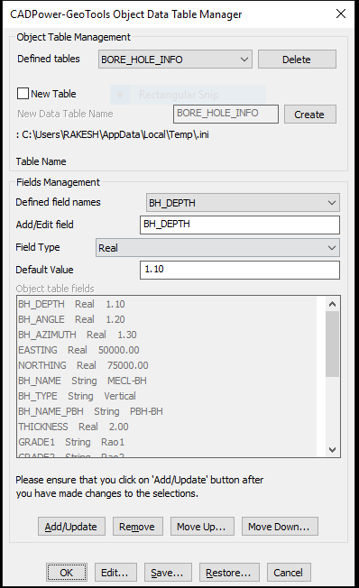
The CP_DATAMAN command is used to define a simple XDATA based database which operates entirely inside your CAD drawing. All data is stored in XDATA attached to entities and the database definition is provided in a simple INI file.
A sample structure of the INI file looks like this. Explanation about the syntax is provided after each section.
[*RECORD]
Name=BAR_INFO
Type=XDATA
FIELD=Section,String,1000
FIELD=Weight per unit length,Real,1000.0
FIELD=Cost per unit length,Real,500.0
FIELD=Supplier,String,Tata
FIELD=Photo,Link,(none)
[*RECORD_END]
The [*RECORD]....[*RECORD_END] section defines the database strcture. It is defined with lines having <Parameter>=<Value> syntax.
The 'Name' parameter specifies the database name (or the XDATA application name).
The 'Type' parameter indicates the type of database. In this case, it is 'XDATA'. In future, additional database types like 'ATTRIBUTES' etc will be introduced.
[*FIELD_VALUES]
Name=Section
Values=ISMB 200
Values=ISMB 300
Values=ISMC 400
[*FIELD_VALUES_END]
The [*FIELD_VALUES]....[*FIELD_VALUES_END] section defines the fields structure. This is also defined with <Parameter>=<Value> syntax.
The 'Name' parameter specifies the Field Name.
The 'Values' parameter defines the commonly used values for the field. These will appear in a pull-down menu when the CP_DATAMAN command is run.
There will be multiple [*FIELD_VALUES] section in the INI file, as many as the number of fields. However, it is not mandatory to define the [*FIELD_VALUES]. If this section is not defined for a field, there will be no pull-down menu options while entering data for the field.
The CP_DATAMAN command now supports an additional data type which allows files on the disk, server or cloud to be attached to selected objects. Using this option, you can create a link between an external file and your CAD entities. There is also a 'Show' option which allows to display the linked file automatically by launching the application with which it is associated.
For example, in the [RECORD] section above, the FIELD Photo is defined as a Link type. This means that it will offer Browse and Show buttons to select a file to be linked with the object and display it using the associated application.
Toolbar : Build Tools ![]()
Menu : CADPower -> Build -> CADPower Object Data -> Attach Data CmdLine : CP_ATTACHDATA
Description Pending
Toolbar : Build Tools ![]()
Menu : CADPower -> Build -> CADPower Object Data -> Detach Data CmdLine : CP_DETACHDATA
Description Pending
Toolbar : Build Tools ![]()
Menu : CADPower -> Build -> CADPower Object Data -> Edit Data CmdLine : CP_EDITDATA
Description Pending
Toolbar : Build Tools ![]()
Menu : CADPower -> Build -> CADPower Object Data -> Copy Object Data CmdLine : CP_COPYDATA
Description Pending
Toolbar : Build Tools ![]()
Menu : CADPower -> Build -> CADPower Object Data -> Import Object Data from CSV files CmdLine : CP_LABELDATA
Description Pending
Toolbar : Build Tools ![]()
Menu : CADPower -> Build -> CADPower Object Data -> Query Object Data CmdLine : CP_QUERYDATA
Description Pending
Toolbar : Build Tools ![]()
Menu : CADPower -> Build -> CADPower Object Data -> Export CADPower Object Table Data to ASCII (CSV) files CmdLine : CP_CPOD_EXPORT
Description Pending
Toolbar : Build Tools 
Menu : CADPower -> Build -> CADPower Object Data -> Import Object Data from CSV files CmdLine : CP_CPOD_IMPORT
Description Pending
Toolbar : Build Tools 
Menu : CADPower -> Build -> CADPower Object Data -> Create tabular CAD data from object table data CmdLine : CP_CPOD_TABLEDATA
Description Pending
Toolbar : Build Tools
Menu : Build -> CADPower Object Data Management -> Copy and Paste from Excel CmdLine : CP_EXCELCOPYPASTE
Description Pending
Toolbar : Build Tools
Menu : Build -> CADPower Object Data Management -> Create attributed block / object table from Excel CmdLine : CP_EXCEL2ATTBLK
Description Pending
Toolbar : Build Tools 
Menu : CADPower -> Build -> CADPower Object Data -> Query and Insert data from Excel sheet CmdLine : CP_EXCELQUERY
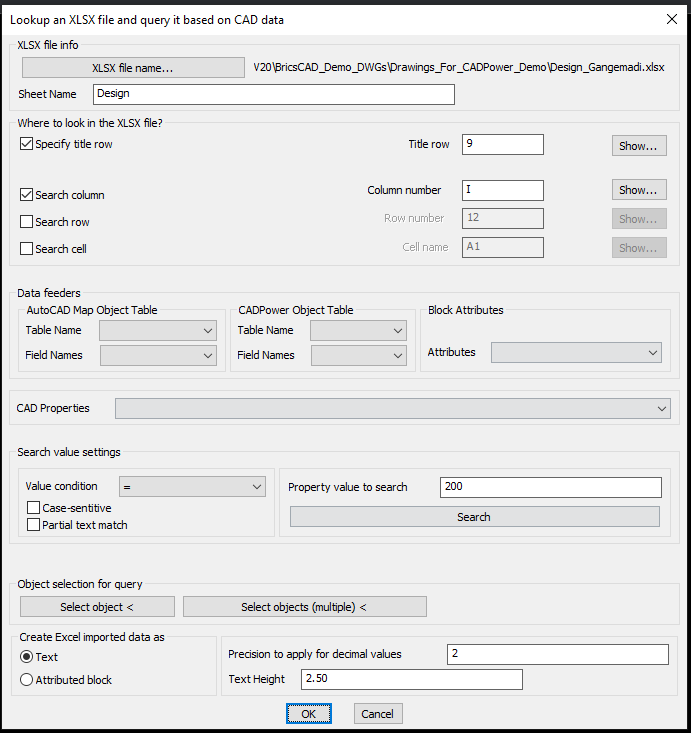
CP_EXCELQUERY dialog
The CP_EXCELQUERY command is a multi-purpose command to read a specified sheet from XLSX files and query the data based on rows and columns, match them with CAD data using logical conditions and generate tables or MTEXT or attributed block with the returned information.
The use-case for this: What is the problem it solves?
You have an Excel sheet and you have a CAD drawing. You need to match the content in the Excel sheet based on your CAD data and pull out relevant information. This command has the solution.
There are two sets of information that you need to specify in this main dialog box.
The first set pertains to the XLSX workbook name and the SheetName where you need to look for the data.
Next, you need to specify the rows and columns you want to search.
The first item in this list is the location of the Title row: usually Excel sheets have the title info specified in one of the rows. You need to specify that row number here.
In the Search Column and Search Row sections, you need to specify a row or column name that you want to quick-search. The results are displayed instantly in a popup window opened by the Show buttons and copied to clipboard and/or placed as MTEXT or attributes block on the drawing. There is a Search Cell option also to retrieve the value of a single cell.
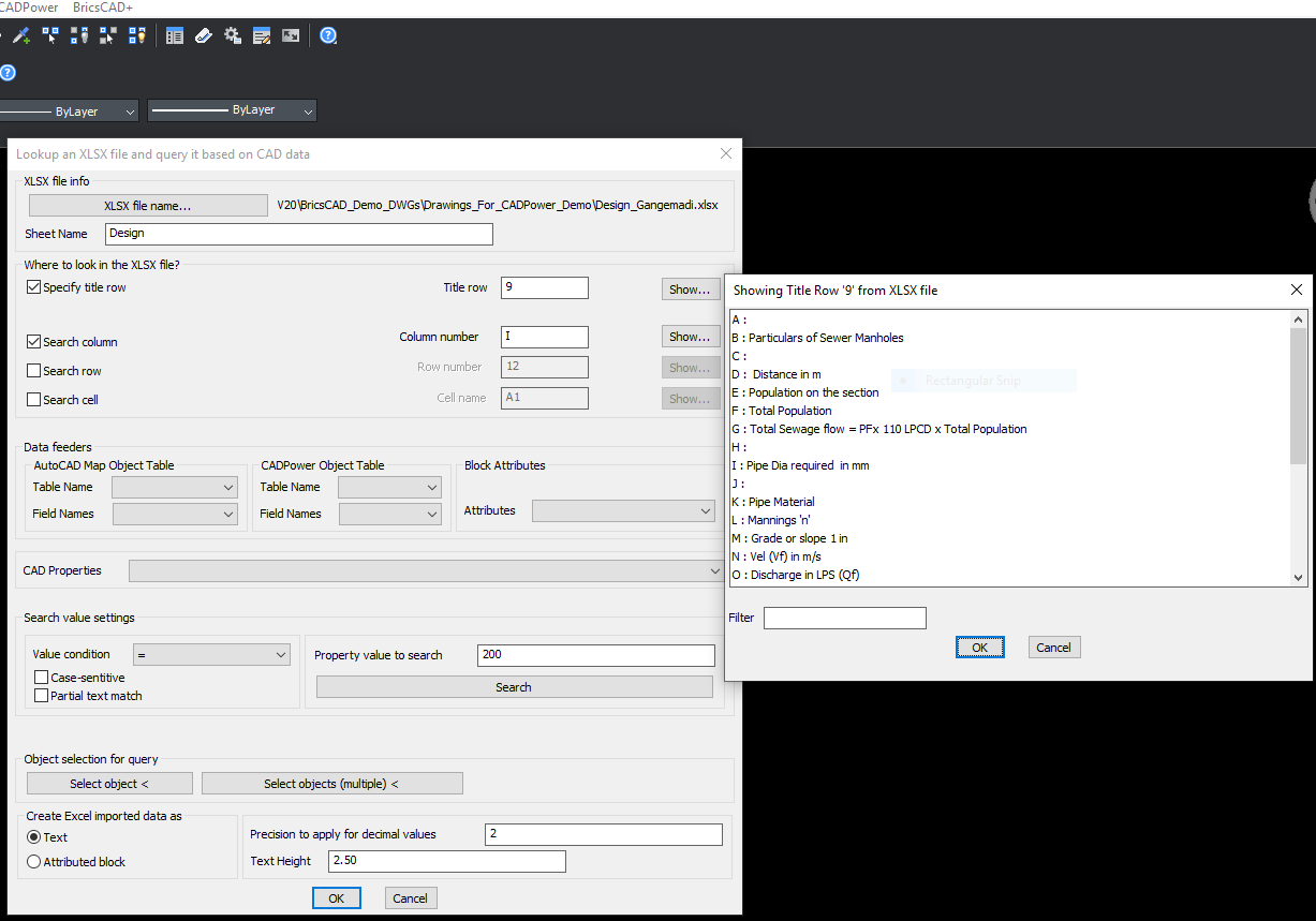
The TitleRow Info from the Excel sheet
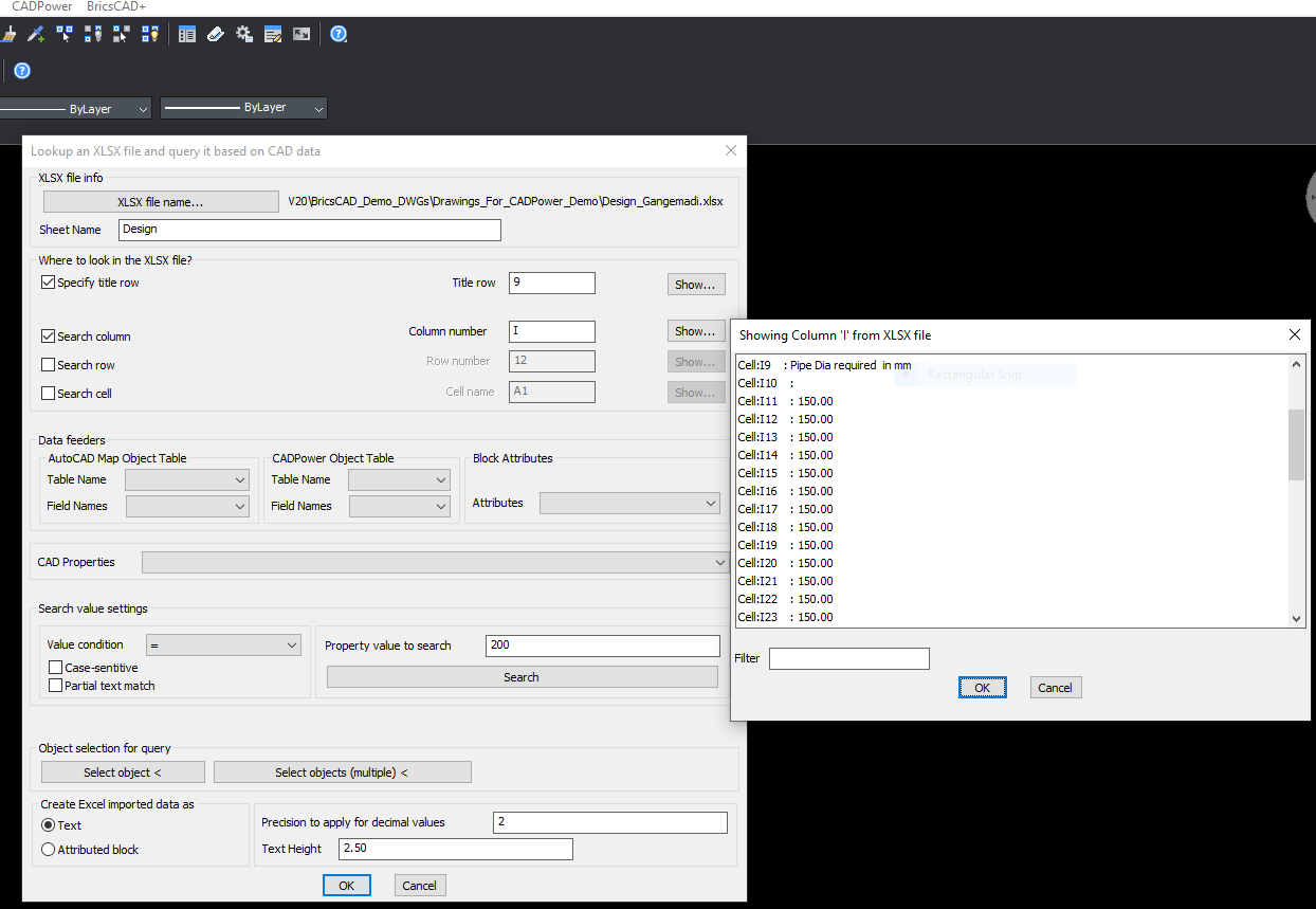
The results of a queried column

The results of a query from XLSX displayed as table in CAD
The next section is called Data Feeders where you can get CAD data from selected object(s) or enter your own independent search data.
Data from your drawing can either come from an AutoCAD Map Object table, CADPower object data or from inherent CAD properties like Length, Area, block attribute, text value, radius, elevation, color, rotation angle etc. The complete list of CAD properties that you can use are shown in the image below:
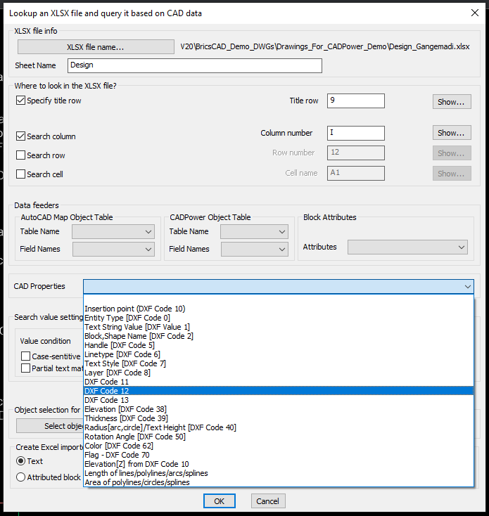
CAD properties that can be queried from XLSX
The next set of information you need to provide is about the CAD entity that you want to use for query. Clicking on the Select button allows you to pick an entity that will offer its internal CAD properties or attached object table or attribute data for query. You need to make the right selections from the Data Feeders and get the property value that you want to query.
You can also specify logical operators on the data and perform the query based on whether you want an exact match, less than or greater than or not equal to the value (for integer and real values). For string values, you can search based on their case, or even partial search and so on.
All the search conditions you specify here will be taken into consideration when searching the XLSX data.
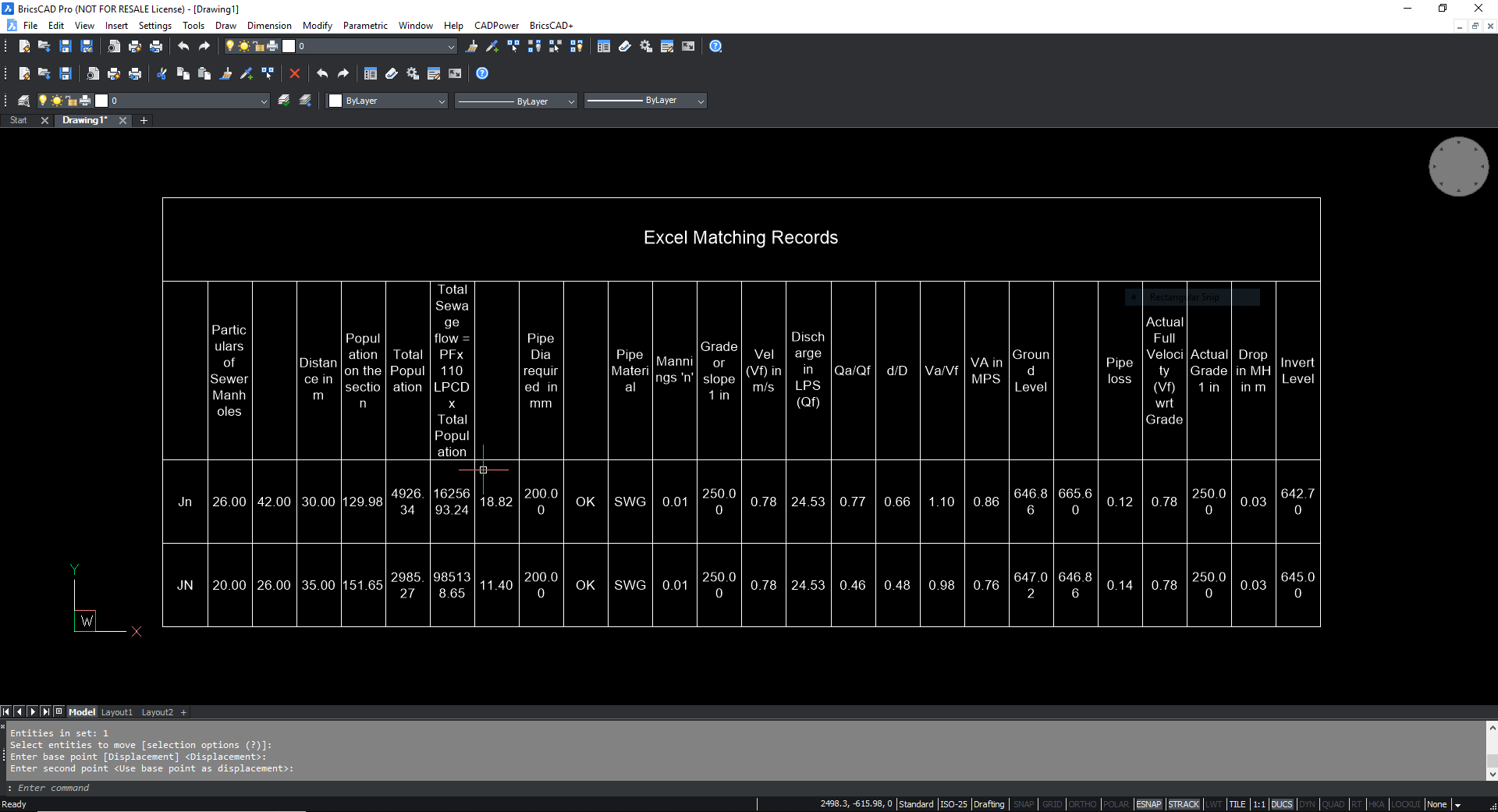
Excel data read in and displayed as table
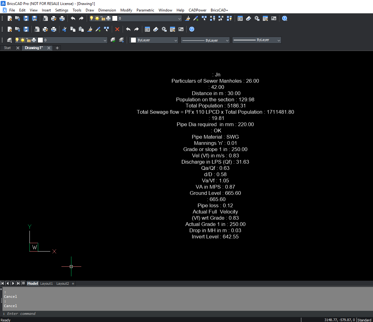
Excel data read in and displayed as MTEXT
Watch: ![]()
Toolbar : Build Tools ![]()
Menu : CADPower -> Build -> CADPower Object Data -> Transfer block attributes to CADPower object table data CmdLine : CP_CPOD_ATT2OD
Descrption Pending