Draw Tools
 Toolbar : Draw Tools
Menu : CADPower -> Draw -> Geometry -> Tapered Lines  CmdLine : CP_CREATETAPER
The CP_CREATETAPER command is used to create tapered polylines (with specified widths at each end) OR convert existing lines, polylines and arcs into tapered polylines.
Note: CP_CREATETAPER command can convert only two vertex polyline/arc into tapered polyline/arc. Toolbar : Draw Tools 
Menu : CADPower -> Draw -> Geometry -> Draw Slot CmdLine : CP_SLOT
The CP_SLOT command is useful for quickly drawing a slot with specified center point, width, length and rotation angle.
Note: The slot is rotated about its centroid.
Toolbar : Draw Tools 
Menu : CADPower -> Draw -> Geometry -> Draw Helix CmdLine : CP_HELIX
Draws a helical curve, with the helix parameters as shown in the dialog box above.
Resolution: Specify the number of tesselations (SURFTAB1) in one circle of the helix
Toolbar : Draw Tools 
Menu : CADPower -> Draw -> Geometry -> Draw a parabolic curve CmdLine : CP_PARABOLA
The CP_PARABOLA command draws a parabolic curve. You should specify the start and end points of the parabola and the vertex point and a parabolic curve is fitted between them
Toolbar : Draw Tools 
Menu : CADPower -> Draw -> Geometry -> Draw an involute curve CmdLine : CP_INVOLUTE
The CP_INVOLUTE command draws an involute curve.
Grain Tolerance: The grain tolerance is the angle interval in degrees at which the points of the involute curve is computed.
Start angle: The start angle defines the AutoCAD / BricsCAD angle (direction) at which the involute curve begins.
Angle to trace: The angle to trace defines the angle in degrees through which the involute curve should be traced.
Toolbar : Draw Tools 
Menu : CADPower -> Draw -> Geometry -> Draw a tube CmdLine : CP_TUBE
The CP_TUBE command creates a 3DSOLID tube with specified center point, inner radius, outer radius and height.
Toolbar : Draw Tools 
Menu : CADPower -> Draw -> Geometry -> Draw a truncated cone CmdLine : CP_TRUNCCONE
The CP_TRUNCCONE command creates a 3DSOLID truncated cone with specified bottom radius, top radius and height.
Toolbar : Draw Tools 
Menu : CADPower -> Draw -> Geometry -> Draw a perpendicular line CmdLine : CP_PERP
The CP_PERP command draws a perpendicular line from the picked point on a curve.
Toolbar : Draw Tools 
Menu : CADPower -> Draw -> Geometry -> Draw a rectangle with diagonals CmdLine : CP_DBOX
This is a quick command to draw a rectangle with diagonals. Pick the two corners of the rectangle and optionally specify the rotation angle at which to align the rectangle
Toolbar : Draw Tools 
Menu : CADPower -> Draw -> Geometry -> Extend lines to a boundary CmdLine : CP_XLINES
The CP_XLINES is used to draw lines from a selected point to a horizontal, vertical or inclined boundary line..
Toolbar : Draw Tools 
Menu : CADPower -> Draw -> Geometry -> Draw tangents to curves CmdLine : CP_TANCURVE
The CP_TANCURVE command provides a quick way to draw tangents to curves like arcs, polylines, splines etc. Tangents can be drawn at the ends of the curve or at the picked point on the curve with a fixed or specified length as shown in the dialog box.
Note: The “Intersect” option under “Tangent Length” is not yet implemented.
Toolbar : Draw Tools 
Menu : CADPower -> Draw -> Geometry -> Equation of a Line CmdLine : CP_LINEEQ
The CP_LINEEQ command is for your kids, or for a one-off mathematical task. It plots the equation of a line as per the formula y=mX + B. You have to specify the values for the constants M and B, the start and end limits for your X values, and an increment value for X. The equation of the line is plotted as a polyline, and is labeled with the equation parameters y=mx + b.
Toolbar : Draw Tools 
Menu : CADPower -> Draw -> Geometry -> Construction Grid CmdLine : CP_CGRID
The CP_CGRID command creates a construction grid with labels. It has the option of creating Horizontal, Vertical, Inclined or Bi-Directional grid interactively (at pick points) or automatically (to fill a rectangular space). It is also possible to create interactive and automatic circular grids also.
In interative mode, the distance or angular inputs can be provided which specify the spacing between the grid lines. For example, while drawing rectangular grids, it is possible to draw the next grid line by entering the perpendicular distance from the last drawn grid line. A positive value draws to the right of the first defining grid line and a negative value draws to the left of the grid line. Similarly, while drawing interactive circular grids, it is now possible to enter the next grid line relative to the last grid line by specifying the distance from the inner grid point or the outer grid point. A value of '50i' indicates a distance of 50 from the inner point while '100o' indicates 100 distance from the outer grid point. Angular alignments also can be created. For example, entering '20a' creates the next grid line at an angle of 20 degrees clock-wise to the last drawn grid line. '-20a' would draw it counter-clockwise.
There are also options to create cross-grid points in interactive circular mode. Cross grid points also can be created by pick or by entering distances from inner or outer grid points as indicated above.
Watch: ![]()
Toolbar : Draw Tools 
Menu : CADPower -> Draw -> Geometry -> Rectangle with dimensions CmdLine : CP_RECTLB
The CP_RECTLB command creates a rectangle and places a 'Length' X 'Breadth' annotation inside it. You can specify a primary drawing unit as well as additional alternate units and have the annotation appear in either one or both units. This is a 'quick and dirty tool' to draw and place measurements on rectangular spaces in m, mm, cm, ft, inches, yards or combinations of any of these two units to create a multi-units dimension. Additionally, options exist to annotate imperial units in the style 6' 6" or as 6.5 ft. This is a handy tool for architects and engineers. The 'DimExternal' and 'DimInternal' options have been implemented. It is now possible to create the dimensions of the rectangle either outside (as horizontal and vertical dimensions) or Inside (as aligned dimensions).
.
Toolbar : Draw Tools 
Menu : CADPower -> Draw -> CAD Objects -> Enhanced, easy 3D points command CmdLine : CP_EASY3DPOINT
CP_EASY3DPOINT allows 3d point objects to be created easily. It mimics the POINT command but allows the elevation value to be entered at each point pick prompt.
Toolbar : Draw Tools 
Menu : CADPower -> Draw -> CAD Objects -> Enhanced, easy 3D polyline drawing tool CmdLine : CP_EASY3DPOLY
CP_EASY3DPOLY allows 3d polylines to be constructed easily by providing an easy-to-use interface that allows for elevation values of each point to be entered without having to use .xyz osnap filters. Imagine you are digitizing the values of a surveyed path which is in 3d and available only in paper form. This command allows each point to be picked and the Z value entered in an easy manner. Or if you estimating the elevations of each point based on nearby objects, this command can be used very effectively.
Command: CP_easy3dpoly
Draw 3d polyline with elevation prompts.
From point: (pick a point)
Enter vertex elevation <0.00>: 5.6
Close/Undo/Auto:<Endpoint of line>:a
Enable Automatic elevation increment/decrement? [ Yes/No ] <No>:y
Enter increment[+]/decrement[-] value <1.00>:
[-1.00, CurZ=6.60] Close/Undo/Auto:<Endpoint of line>:
[-1.00, CurZ=7.60] Close/Undo/Auto:<Endpoint of line>:
[-1.00, CurZ=8.60] Close/Undo/Auto:<Endpoint of line>:
[-1.00, CurZ=9.60] Close/Undo/Auto:<Endpoint of line>:
The CP_EASY3DPOLY command can also automatically calculate the elevation for subsequent points based on a constant increment or decrement from the current elevation. The current elevation and the current increment of decrement setting can be viewed in real-time while running this command.
Toolbar : Draw Tools 
Menu : CADPower -> Draw -> CAD Objects -> Enhanced, easy 3DFace drawing tool CmdLine : CP_EASY3DFACE
The CP_EASY3DFACE command allows a quick and easy way to create 3DFACE objects by allowing elevation values of the 3dFACE vertices to be entered directly without having to use .xyz osnap filter.
Toolbar : Draw Tools 
Menu : CADPower -> Draw -> CAD Objects -> Enhanced, easy 3DSpline drawing tool CmdLine : CP_EASY3DSPLINE
The CP_EASY3DSPLINE command allows a quick and easy way to create 3d Spline objects by allowing elevation values of the vertices to be entered directly without having to use .xyz osnap filter.
Toolbar : Draw Tools 
Menu : CADPower -> Draw -> Symbology -> Roughen a linear object CmdLine : CP_ROUGHEN
Pick a linear object (line or polyline) and roughen it. The roughened line contains randomly created zig-zags on either side of the center line
Toolbar : Draw Tools 
Menu : CADPower -> Draw -> Symbology -> Pattern Placer CmdLine : CP_PATTERNPLACER
The CP_PATTERNPLACER command is used to arrange a pattern inside a polygonal boundary in a row-wise manner. The command works with blocks. You must first create a block that represents one motif of the repeating pattern. The motif must be drawn in a direction facing the CAD 0.0 degree direction (east) and the insertion point must be at the left hand center of the motif. The 0.0 degree direction of the motif becomes the flow direction when the pattern is generated on a repeated basis along the row. An X and Y offset is specified to denote where the next row will be positioned (alignment with reference to the adjacent row). Another distance parameter indicates the distance between the two motifs along the row.
Toolbar : Draw Tools 
Menu : CADPower -> Draw -> Symbology -> Create Block table CmdLine : CP_BLOCKTABLE
Creates a preview of blocks in a table.
Toolbar : Draw Tools 
Menu : CADPower -> Draw -> Symbology -> Create Layer table CmdLine : CP_LAYERTABLE
Creates a preview of layers in a table.
Toolbar : Draw Tools 
Menu : CADPower -> Draw -> Rule-Based -> Draw 3D polylines with automatically incrementing / decrementing elevations CmdLine : CP_DRAWPOLYINCRDECR
The CP_DRAWPOLYINCRDECR command is used to create new 3d polylines by automatically incrementing or decrementing vertex elevations. Alternatively, you can specify existing 3d polylines and have their z values automatically incremented or decremented.
3d polyline creation options
Create New: Starts the 3d polyline digitizing command and enables new polylines to be created with incrementing or decrementing elevations.
Update existing: Select existing 3d polylines and update their vertex elevations incrementing or decrementing.
Starting Z value: Specify the starting Z value of the first vertex of the polyline.
Increment/Decrement value: Specify the elevation value to increment or decrement.
Toolbar : Draw Tools 
Menu : CADPower -> Draw -> Rule-Based -> Draws a rectangular box at the current screen extents CmdLine : CP_BOXSCREEN
The CP_BOXSCREEN command creates a closed polyline representing the extents of the current viewport.
Toolbar : Draw Tools 
Menu : CADPower -> Draw -> Rule-Based -> Draws bounding box around selected object(s) CmdLine : CP_BOUNDENT
The CP_BOUNDENT command draws a rectangular bounding box (closed polyline) representing the extents of all selected objects.
Toolbar : Draw Tools 
Menu : CADPower -> Draw -> Rule-Based -> Draw a polyline by joining points in sorted order CmdLine : CP_SORTEDPOLY
The CP_SORTEDPOLY command draws a polyline through selected points sorted in Positive X, Negative X, Positive Y or Negative Y direction.
Sort Order
Increasing X values : Choosing the option draws the polyline in increasing (positive) X direction.
Increasing Y values : Choosing the option draws the polyline in increasing (positive) Y direction.
Decreasing X values : Choosing the option draws the polyline in decreasing (negative) X direction.
Decreasing Y values : Choosing the option draws the polyline in decreasing (negative) Y direction.
Watch: ![]()
Toolbar : Draw Tools 
Menu : CADPower -> Draw -> Rule-Based -> Draw arc-ends to arc-center connections in arcs / polyarcs CmdLine : CP_SHOWPLARCS
Layer to place:
Source: Choosing this option draws arc-ends to arc-center connections in the source layer
Current: Choosing this option draws arc-ends to arc-center connections in the current layer
Specify: Choosing this option allows specifying the layer in which the arc-ends to arc-center connections to be drawn
Select: Clicking on Select button pops up the Select Layer dialog box.
Delete original objects: Checking this box deletes the original source object after drawing arc-ends to arc-center connections
Toolbar : Draw Tools 
Menu : CADPower -> Draw -> Rule-Based -> Draw Hole Table CmdLine : CP_HOLETABLE
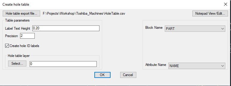
It is now possible to create a hole-table (or hole-chart) in CADPower and export the same into Excel via CSV files.
Hole tables (also known as hole chart) specify the position of holes (or any point of interest, like a punched shape (like polygon) or a placed block (with attributes) within a reference frame (usually a rectangle, but can be any geometry [closed polygon]) and create a table within the drawing and optoinally export the same into an Excel-compatible CSV file.
The holes (or points of interest) are represented as rows in the table and X, Y offset dimensions and other properties of the holes as columns. Circles, points, blocks (with or without attributes) can be represented in a hole-table. A hole-table is a list of coordinates of a 'hole' or 'point of interest' (measured from a specified origin) and serves as a guide for punching operations. Typical properties that can be captured in the hole-table are X & Y coordinates, diameter (for circular holes), block names and/or attribute values.
The Hole table is created as a TABLE object and uses the current TABLE stype properties.
This command also produces a quantity table that quantifies all holes by diameter, all blocks by names and attributes by values and lists the quantities as well. You can use the CP_HOLETABLE tool in many imaginable ways in various situations, and not just as a hole-table as applied to manufacturing.
In addition to creating hole table, this command also creates a Quantity Table. The Quantity table lists all the holes of the same diameter and quantifies them in a table. Similarly, all unique block names and attribute values in the selection are counted and listed in the Quantity table. This helps to identify and quantify the holes in a sheet, be it represented by circles or blocks with an attribute describing the hole.
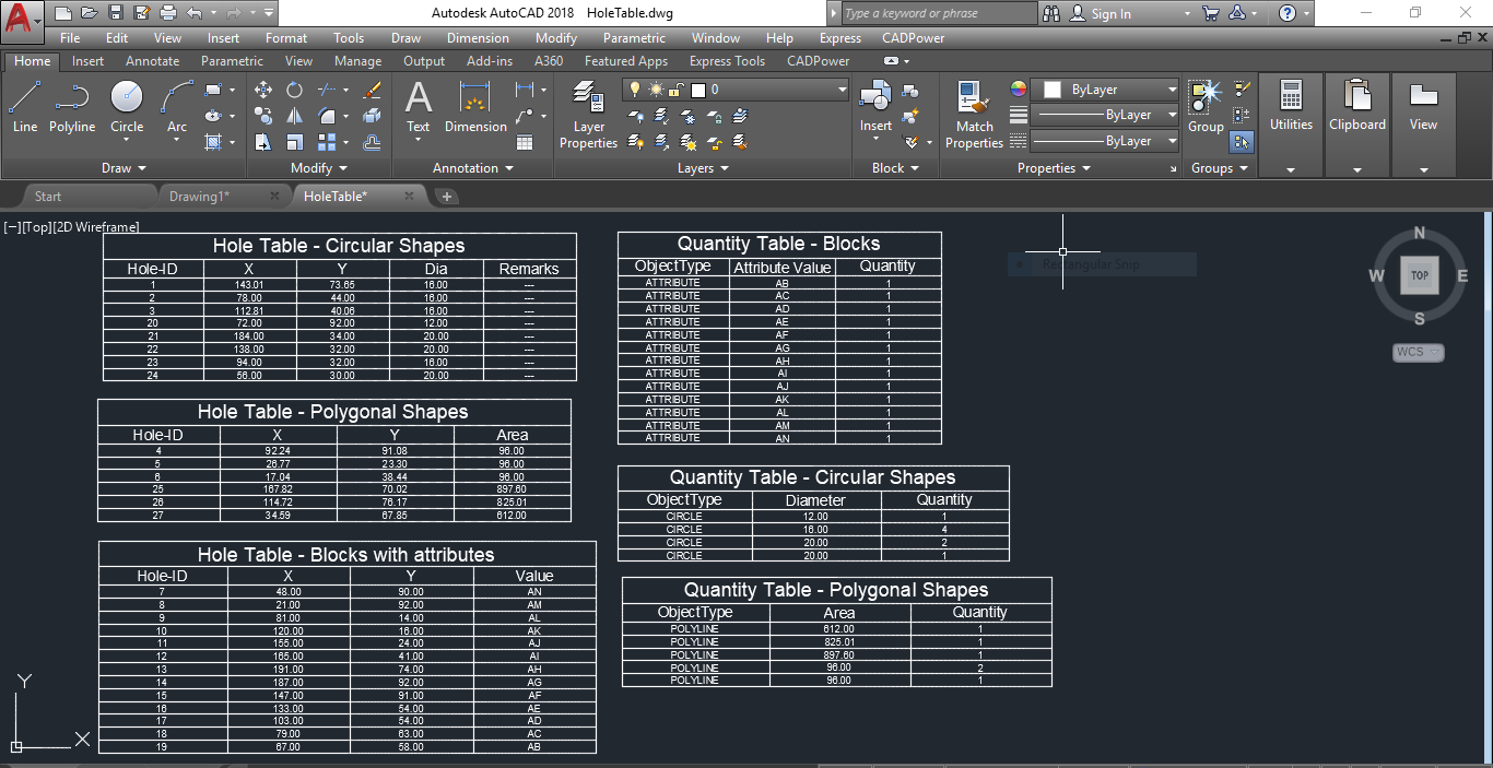
The output fom the CP_HOLETABLE command
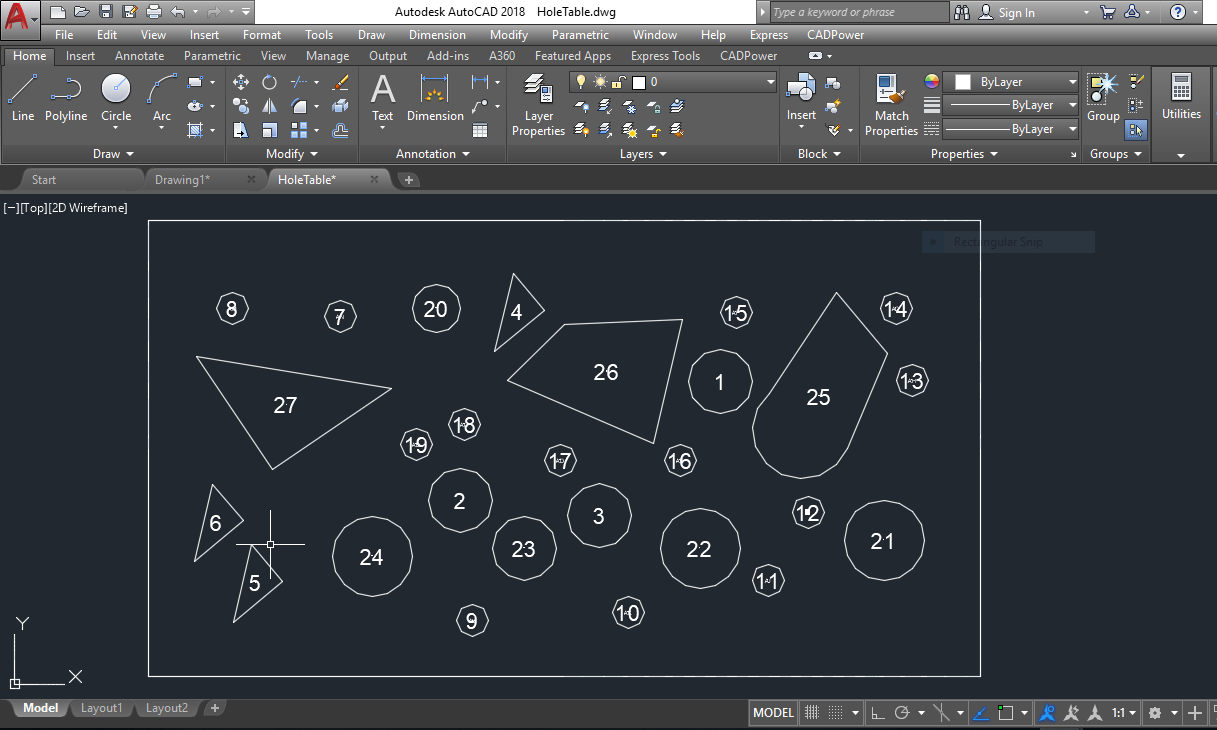
The input data for the CP_HOLETABLE command
Related command: CP_BOM ( CADPower -> BOM/BOQ Tools -> Create Bill of Materials/Quantities): You can use the CP_BOM command to directly import a hole-table CSV file from Excel using the 'Import Table only' option.
Watch: ![]()
Toolbar : Draw Tools 
Menu : CADPower -> Draw -> Rule-Based -> Draw CAM Profile CmdLine : CP_CAM_PROFILE
Description Pending
Toolbar : Draw Tools
Menu : CADPower -> Draw -> Rule-Based -> Draw tool cutting path around a closed boundary CmdLine : CP_CURVEANALYZER
Description Pending
Toolbar : Draw Tools
Menu : CADPower -> Draw -> Rule-Based -> Draw nested boundary CmdLine : CP_NESTEDBOUNDARY
Description Pending
Toolbar : Draw Tools 
Menu : CADPower -> Draw -> Rule-Based -> Draw closed polylines to an exact area CmdLine : CP_POLYAREACREATE
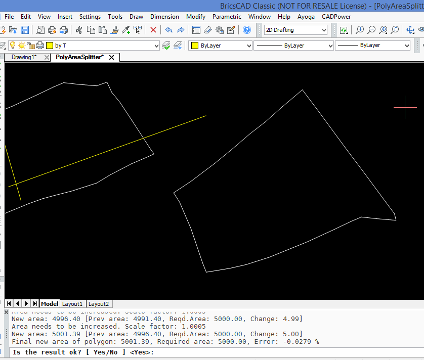
The CP_POLYAREACRATE command creates a closed polyline (polygon) of an exact area. For example, if you have drawn the shape of your polygon but want to scale it up or down such that it measures to an exact area, you can use this command.
The command scales the polygon up or down by a specified amount until the exact area is reached. No more manual trial and error by painstaking methods. This command finds use in many patterning and land parcel planning workflows where you need to create a pre-defined shape of polygon to an exact area. There is both manual as well as automatic method of polygon creating.
 .
.
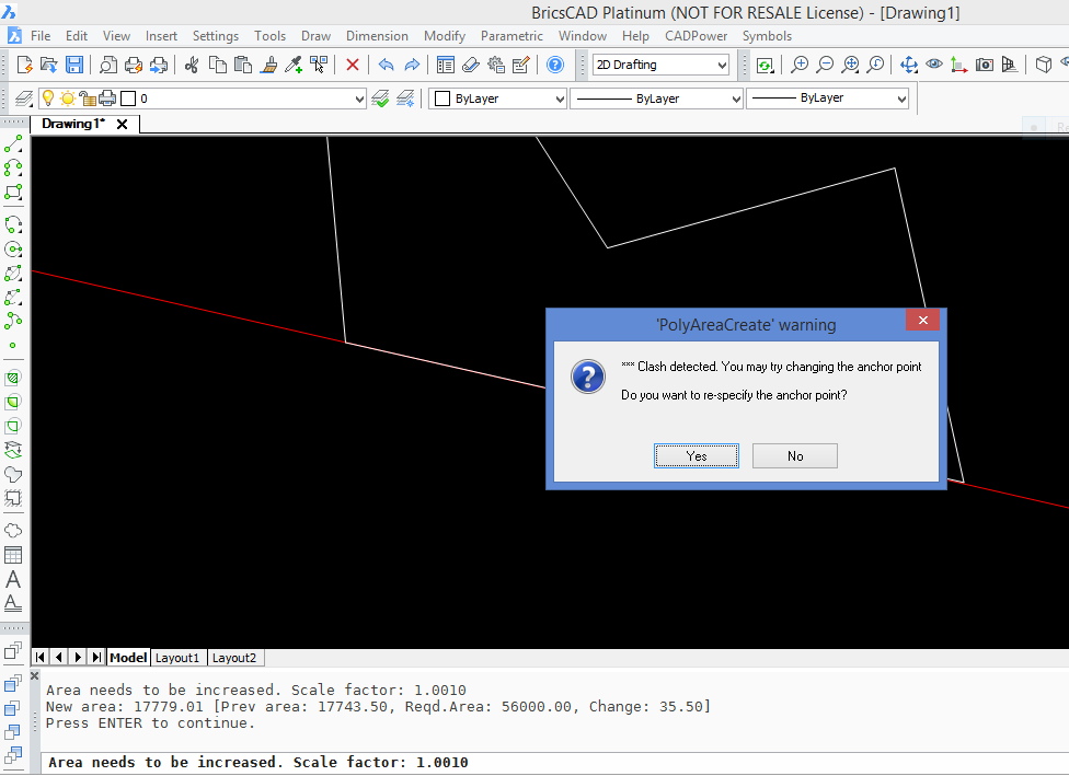
Clash Detection: Often, when you increase the area of a polygon by incremental amounts, it is necessary to stop when an adjoining polygon boundary is reached. This is enabled by Clash Detection. When enabled, the command stops when the polygon touches a neighboring polygon, line or arc boundary. At this point, you have the option to change the anchor point and re-scale the polygon in a different direction or accept the existing one and exit the command.