Miscellaneous Tools
 Toolbar : Miscellaneous Tools (CP)
Menu : CADPower -> Miscellaneous -> File Management -> File Manager
 CmdLine : CP_FILEMAN
The CP_FILEMAN command provides an easy interface to copy, move, erase, touch and count your files.
Toolbar : Miscellaneous Tools (CP)
Menu : CADPower -> Miscellaneous -> File Management -> DWG browser, with thumbnail preview
CmdLine : CP_DWGBROWSER
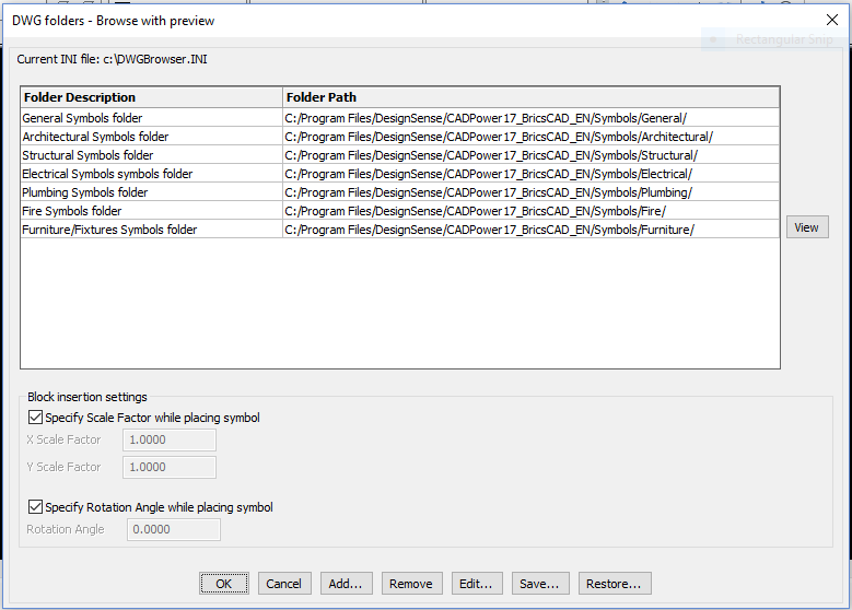
The CP_DWGBROWSER command is used to browse DWG files from multiple folders with a thumbnail preview image of each file. The selected file can then be inserted into the current drawing. You can specify a set of your favourite folders, give them a description each and store the settings in an ASCII INI file for subsequent retrieval. By default, the file will be called DWGBROWSER.INI and will reside (or be created) in your current drawing folder. Additional block insert parameters like x, y scale factors and rotation angles can be pre-set or specified on-screen as desired.
Toolbar : Miscellaneous Tools (CP) 
Menu : CADPower -> Miscellaneous -> File Management -> Detaches all unreferenced X-Refs and binds all others into current DWG
CmdLine : CP_BINDXREF
This is a cleanup tool that removes all unresolved external references and bind all valid attached xrefs. This is often the most common requirement and a procedure followed before sending a drawing containing XREFs to someone outside the office.
Toolbar : Miscellaneous Tools (CP) 
Menu : CADPower -> Miscellaneous -> File Management -> Batch process multiple drawings with scripts
CmdLine : CP_BATCHPROCESS
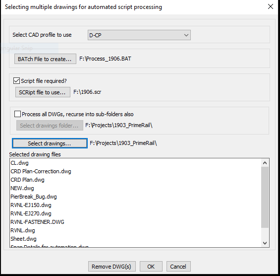
The CP_BATCHPROCESS command is used to select multiple DWG files and create a .BAT file to load each one into AutoCAD / BricsCAD and optionally perform automated script processing with as SCR file. The script file must already exist (if checked) while the batch file is created by this command to open your CAD software with the selected DWG files with the specified AutoCAD / BricsCAD profile and the script file.
If you check the box Process all DWGs, recurse into sub-folders also CP_BatchProcess command can do a recursive search starting from the selected folder and all folders below it and will create a BATch file to process all the files in one go.
Toolbar : Miscellaneous Tools (CP) 
Menu : CADPower -> Miscellaneous -> File Management -> Multiple DWG inserts
CmdLine : CP_MULTINS
The CP_MULTINS command is used to select at once multiple DWG files from one or more folders and insert them all into the current drawing.
The Remove All option clears the current selection of all drawings.
The Explode option allows each inserted drawing to be exploded upon insert into the current drawing.
Toolbar : Miscellaneous Tools (CP) 
Menu : CADPower -> Miscellaneous -> File Management -> Multiple drawings Xrefs
CmdLine : CP_MXREF
The CP_MXREF command is used to attach multiple DWG files at once as external reference (XREF)
Toolbar : Miscellaneous Tools (CP) 
Menu : CADPower -> Miscellaneous -> File Management-> EXIF Data View/Extract
CmdLine : CP_READEXIF
CP_READEXIF is a generic tool to extract all the EXIF information from files and display it on the dialog box or save it into a .EXIF file.
EXIF stands for Exchangeable Image File Format. EXIF is a standard that specifies the formats for images, sound, and ancillary tags used by digital cameras (including smart phones), scanners and other systems handling image and sound files recorded by digital cameras. The GeoTIFF file format used in GIS and mapping is an example of how geo-referencing information is stored inside TIFF file using EXIF tags.
Watch: ![]()
![]()
Toolbar : Miscellaneous Tools (CP) 
Menu : CADPower -> Miscellaneous -> File Management-> INI Editor
CmdLine : CP_INIEDITOR
The CP_INIEDITOR command is used to edit INI files used by various CADPower commands. While some of the commands have a built-in access to an 'Edit' button, many don't. If you need to edit an INI file, you can use this tool.
Toolbar : Miscellaneous Tools (CP) 
Menu : CADPower -> Miscellaneous -> CSV Editor
CmdLine : CP_CSVEDITOR
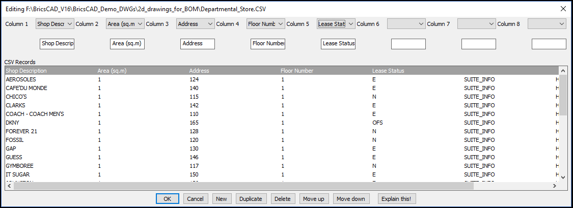
CP_CSVEDITOR is used to edit comma delimited ASCII text files within the CAD editor. The current version allows to edit CSV files with a max. 8 columns of CSV data. The data is presented in a dialog box and each column can be edited by entering a new value in the edit box or choosing one from the pull-down menu. A pre-defined set of probable values can be defined and supplied to the command.
Toolbar : Miscellaneous Tools (CP) 
Menu : CADPower -> Miscellaneous -> File Management -> Move .bak files to a folder
CmdLine : CP_MOVEBAK (or MOVEBAK)
BricsCAD lacks the MOVEBAK command of AutoCAD. This is now available in BricsCAD via CADPower. The CP_MOVEBAK command allows the .bak folder to be specified via a dialog box, while the MOVEBAK command does the actual moving of .BAK files to the designated folder.
Toolbar : Miscellaneous Tools (CP) 
Menu : CADPower -> Miscellaneous -> File Management -> Drawing Recovery Manager
CmdLine : CP_RECOVERYMANAGER
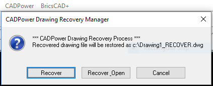
The familiar drawing recovery manager from AutoCAD is now available in BricsCAD via CADPower. The CP_RECOVERYMANAGER is a FREEWARE command and available in the BricsCAD version only. It provides a work-around for the Drawing Recovery tool that is available in AutoCAD and which is missing in BricsCAD. This tools tracks the auto-save file that is created in the TEMP folder and restores the latest version available and offers to copy it to the same folder as your current drawing. The recovered file has a name _RECOVER.dwg and it functions almost identically to the AutoCAD tool.
Toolbar : Miscellaneous Tools (CP) 
Menu : CADPower -> Miscellaneous -> Export -> Layers to DWG
CmdLine : CP_LYRS2DWG
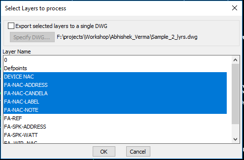
This command exports the contents of each layer into a drawing by WBLOCKing them into their own DWG file and whose filename is the same as the layer name.
Toolbar : Miscellaneous Tools (CP) 
Menu : CADPower -> Miscellaneous -> Export -> Split a drawing into smaller parts
CmdLine : CP_DWGSPLIT
The CP_DWGSPLIT command uses the WBLOCK command to split a given selection of objects into smaller drawing units. The drawing can be split either into a number of equal parts or containing a specified number of objects.
Toolbar : Miscellaneous Tools (CP) 
Menu : CADPower -> Miscellaneous -> Export -> Sort ASCII Files
CmdLine : CP_FILESORT
The CP_FILESORT command allows an ASCII file to be sorted based on data that can be defined either as a field number (separated by a delimiter) or based on start and end column numbers. The sort type can numeric or character.
Toolbar : Miscellaneous Tools (CP) 
Menu :CADPower -> Miscellaneous -> CAD Procedures -> First Set -> Match Properties
CmdLine : CP_MATCH
The CP_MATCH command matches properties of source and target objects. You can select the properties you want copied (or set) from the source to target object(s). Target object selection can be a single or multiple objects as specified in the dialog box
AutoCAD command: MATCH (for setting properties), MA (to start the command)
Toolbar : Miscellaneous Tools (CP) 
Menu : CADPower -> Miscellaneous -> CAD Procedures -> First Set -> Align Objects
CmdLine : CP_OBJALIGN
The CP_OBJALIGN command helps to align a selection of objects to a justification. CADPower applies an "extents" computation of the objects and based on these extents, the objects are moved (aligned) to share a common datum. The justifications that can be applied are the nine positions of text alignment viz, Top Left/Center/Right, Middle Left/Center/Right and Bottom Left/Center/Right.
The alignment operation can be applied on the whole selection as a single unit or on each object in the selection set individually.
Toolbar : Miscellaneous Tools (CP) 
Menu : CADPower -> Miscellaneous -> CAD Procedures -> First Set -> Scale objects (unequally) in X, Y and Z directions
CmdLine : CP_XYZSCL
The CP_XYZSCL command performs non-uniform scaling of objects with specified X, Y and Z scale factors and a user-specified base point or you can use the 'R-Relative' option to specify scale factors in X and Y direction. This is similar to the SCALE command except that you can specify unequal scale factors in X, Y and Z directions.
Tech Info: The command does not work with blocks containing 3DSOLID objects because of an AutoCAD / BricsCAD limitation in older versions.
Toolbar : Miscellaneous Tools (CP) 
Menu : CADPower -> Miscellaneous -> CAD Procedures -> First Set
CmdLine : CP_ScaleToUnity
Description Pending
Toolbar : Miscellaneous Tools (CP)
Menu : CADPower -> Miscellaneous -> CAD Procedures -> First Set -> Create a mean (averaged) point from cluster of points
CmdLine : CP_MEANPOINT
The CP_MEANPOINT command creates a mean point from selected multiple points and provides an option of connecting each point with the mean point by a line
Toolbar : Miscellaneous Tools (CP) 
Menu : CADPower -> Miscellaneous -> CAD Procedures -> First Set -> Flip reverse elevations(Z) from selected objects
CmdLine : CP_FLIPZ
The CP_FLIPZ command will reverse the z value sign of selected lines, polylines, point, text, 3dfaces, solids etc. So, an elevation of +2 would become -2 and vice-versa
Toolbar : Miscellaneous Tools (CP) 
Menu : CADPower -> Miscellaneous -> CAD Procedures -> First Set -> Round Off values from Point/Lines
CmdLine : CP_ROUNDOFF
The CP_ROUNDOFF command allows points, lines, polylines, blocks, text and shape objects to have their co-ordinates rounded off to the desired number of decimal places.
Toolbar : Miscellaneous Tools (CP) 
Menu : CADPower -> Miscellaneous -> CAD Procedures -> First Set -> Extract (single entity) from Xref
CmdLine : CP_XTRACT
The CP_XTRACT command is used to extract entities from within a block or an XREF object. This command has been enhanced and improved significantly in V 18.02. You can now extract from XREF/blocks which have been scaled and rotated as well. The only limitation is that you cannot extract from non-uniform scaled blocks. It is also possible to place the extracted object either at the original location or move it interactively to a new location. This behavior is controlled by a new command called CP_XTRACT_SETTINGS, which is available only on the command line and not in the menus.
Upon running CP_XTRACT command, the availability of the CP_XTRACT_SETTINGS command is mentioned through a command line message. While using CADPower-GeoTtools, it always helps to keep an eye on the command line for important informative messages.
The CP_XTRACT command allows extraction of LINE, POINT, ARC, SHAPE, POLYLINE, SPLINE, TEXT, LWPOLYLINE and ATTRIBUTE objects.
Watch: ![]()
Toolbar : Miscellaneous Tools (CP) ![]()
Menu : CADPower -> Miscellaneous -> CAD Procedures -> First Set -> Extract selected layers from multiple XREFs
CmdLine : CP_XTRACTXREFLAYERDLG
Description Pending
Toolbar : Miscellaneous Tools (CP) 
Menu : CADPower -> Miscellaneous -> CAD Procedures -> First Set -> Explode objects - Retain object table and extended entity data
CmdLine : CP_XP_RETDAT
The CP_XP_RETDAT command is used to explode polylines, blocks, hatches, regions and mulitple polygon and retain the extended entity and object table data contained in them.
Toolbar : Miscellaneous Tools (CP) 
Menu : CADPower -> Miscellaneous -> CAD Procedures -> First Set -> Report areas covered by HATCH objects
CmdLine : CP_HATCHAREA
The CP_HATCHAREA command produces a report of selected hatch objects. It shows the area covered by each class of hatch pattern as well as number of hatch objects in each pattern, and additional information about solid/gradient hatches, color tones etc.
Toolbar : Miscellaneous Tools (CP) 
Menu : CADPower -> Miscellaneous -> CAD Procedures -> First Set -> Flip ECS of arc with negative normals
CmdLine : CP_FLIPARCS
The CP_FLIPARCS command will reverse the direction of all normals of selected ARCs which are pointing in the negetive WCS direction. Running this command will make the normals positive (in the direction of positive Z axis of WCS).
Toolbar : Miscellaneous Tools (CP) 
Menu : CADPower -> Miscellaneous -> CAD Procedures -> First Set -> Change object visibility
CmdLine : CP_VISIBLE
The CP_VISIBLE command converts CAD graphical objects from a visible state to invisible state and back. The visibility state is set on the command line by means of the (V)isible or (I)nvisible keyword.
Toolbar : Miscellaneous Tools (CP) 
Menu : CADPower -> Miscellaneous -> CAD Procedures -> First Set -> Change Dimension Precision
CmdLine : CP_DIMPREC
The CP_DIMPREC command can be used to change the linear precision of selected dimension objects.
Toolbar : Miscellaneous Tools (CP) 
Menu : CADPower -> Miscellaneous -> CAD Procedures -> First Set -> Re-Create hatch boundaries from HATCH object
CmdLine : CP_HATCHBOUND
The CP_HATCHBOUND re-creates the boundaries from a HATCH object. This can be used as a handy tool to modify the hatch when the comprising boundary objects are not available.
Toolbar : Miscellaneous Tools (CP) 
Menu : CADPower -> Miscellaneous -> CAD Procedures -> First Set -> Insert vertex in hatch boundary
CmdLine : CP_HATCHINSVX
The CP_HATCHINSVX command is used to add new vertices in hatch boundaries. This is particularly useful for BricsCAD users, who cannot otherwise add vertices to hatch boundaries. If there are multiple hatch boundaries, they are highlighted one by one and you can add vertex in each boundary independently. While adding a vertex, it is possible to do it by mouse-drag and pick or by entering the perpendicular distance from the middle of an existing segment.This is a FREEWARE command and never expires from a CAPower trial.
Watch: ![]()
Toolbar : Miscellaneous Tools (CP) 
Menu : CADPower -> Miscellaneous -> CAD Procedures -> First Set -> Delete vertex from hatch boundary
CmdLine : CP_HATCHDELVX
The CP_HATCHDELVX command deletes vertices from hatch boundaries by a single pick.This is particularly useful for BricsCAD users, who cannot otherwise delete vertices from hatch boundaries. This is a FREEWARE command and never expires from a CAPower trial.
Watch: ![]()
Toolbar : Miscellaneous Tools (CP) 
Menu : CADPower -> Miscellaneous -> CAD Procedures -> First Set -> Remove proxy references from entities
CmdLine : CP_PROXYREMOVER
The CP_PROXYREMOVER command is useful for BricsCAD users who routinely use AutoCAD Civil 3D/raster Design (or similar) drawings that contain references to proxy objects. Certain proxy object references prevent the objects from being copied to the clipboard. This command attempts to fix such errors. Please be aware that this is not a cure-all tool for all proxy related errors. It has ben developed as solution for one such proxy related issue that came up in one of our client locations.
Toolbar : Miscellaneous Tools (CP) 
Menu : CADPower -> Miscellaneous -> CAD Procedures -> Second Set -> Object Chopper
CmdLine : CP_CHOP
The CP_CHOP command chops lines and polylines into a specified number of divisions or creates chops of a specified lengths
Tech Info: CHOP only works with line and polylines objects. They must be de-curved (not fitted or splined) and must not have any arc segments in them. Toolbar : Miscellaneous Tools (CP) 
Menu : CADPower -> Miscellaneous -> CAD Procedures -> Second Set -> Automatic Dimensioning
CmdLine : CP_AUTODIM
The CP_AUTODIM command accepts Lines, Polylines, Arcs, Circles as well as Splines as input and creates automatic dimensions cutting across all these entities.
Toolbar : Miscellaneous Tools (CP) 
Menu :CADPower -> Miscellaneous -> CAD Procedures -> Second Set -> Control 3DFace normals
CmdLine : CP_FACENORMAL
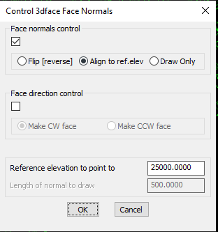
The CP_FACENORMAL command allows control of direction of 3dface normals. If the vertices of the 3dface are in clockwise direction, then the normal is pointing downwards from the plane of the 3dface else if they are in counter-clockwise direction, the normal is pointing upwards from the plane of the 3dface. This command helps to control the normal direction in three ways:
Flip: Flips (reverses) the direction of the face normal
Align to an elevation: Aligns the face normals so as to point in the direction of a specified Z value. What this means is that if the target Z value specified is greater than the maximum Z of all 3dface vertices, the normal will be flipped if necessary so as to point towards the target elevation. This option can be used to make all normals of selected 3dfaces point to a common high or low elevation so that all faces can be made to point inwards or outwards.
Draw: Draws the face normal as it is. No flipping or checking is done. The face normal starts from a point in the plane of the 3dface at the centroid position and is drawn to the specified length in the direction of the normal.
Toolbar : Miscellaneous Tools (CP) 
Menu : CADPower -> Miscellaneous -> CAD Procedures -> Second Set -> Break (split) objects along a polyline
CmdLine : CP_CONTBREAK
The CP_CONTBREAK command is a general purpose command to break a drawing along a boundary. The boundary can be open or closed and must be defined as a polyline.
In the above illustration, you see a screenshot of a very dense contour drawing. By setting up appropriate closed polyline cutting edges (blue lines in the figure above), it is possible to break the contours easily at the boundary of these polygons. Once broken, each part can be exported into it own DWG using the CADPower CP_ESELECT and the WBLOCK command.
Toolbar : Miscellaneous Tools (CP) 
Menu : CADPower -> Miscellaneous -> CAD Procedures -> Second Set -> Zoom to extent of selected object(s) (with 5% margin)
CmdLine : CP_ZOOMENT
The CP_ZOOMENT command zooms to the extents of selected objects with a margin of 5% border on the sides of the current viewport.
Toolbar : Miscellaneous Tools (CP) 
Menu : CADPower -> Miscellaneous -> CAD Procedures -> Second Set -> Delete paper-space layouts
CmdLine : CP_DELETELAYOUTS
The CP_DELETELAYOUTS command will present you with a list of all paper space layouts and you can select multiple layouts and delete them in one go.
Toolbar : Miscellaneous Tools (CP) 
Menu : CADPower -> Miscellaneous -> CAD Procedures -> Second Set -> Delete NULL text
CmdLine : CP_NULLTEXT
The CP_NULLTEXT command gets rid of "ghost" text objects – i.e invisible text objects with an empty (null) string which are often created due to operator and programming errors.
Toolbar : Miscellaneous Tools (CP) 
Menu : CADPower -> Miscellaneous -> CAD Procedures -> Second Set -> Purge all un-used symbols
CmdLine : CP_PALL (also as PUA)
Purges all unreferenced symbols without the confirmation question "Yes/No". Use this command only if you are sure that you do not want ANY unreferenced symbol in your drawing.
Note: CP_PALL command is by default not enabled. To enable it, type CP_DEFMACROS at the command prompt.
Toolbar : Miscellaneous Tools (CP) 
Menu : CADPower -> Miscellaneous -> CAD Procedures -> Second Set -> Remove all unreferenced scales
CmdLine : CP_SCALECLEAN (AutoCAD only)
The CP_SCALECLEAN command removes all un-referenced scales. There is a bug in AutoCAD which causes the SCALELISTEDIT command to keep displaying all scales from any XREF drawings that are already detached. The CP_SCALECLEAN command helps to get rid of all these un-referenced scales by removing the entries from the AutoCAD dictionary.
Toolbar : Miscellaneous Tools (CP) 
Menu : CADPower -> Miscellaneous -> CAD Procedures -> Second Set -> Search / Replace attached URL
CmdLine : CP_REPURL
The CP_REPURL command is used to edit the URLs (hyperlinks) attached to CAD objects. The search/replace interface of CP_REPURL is similar to the one in CP_ZOOMTXT command and allows case-sensitive, partial and interactive search and replace.
Toolbar : Miscellaneous Tools (CP) 
Menu : CADPower -> Miscellaneous -> CAD Procedures -> Second Set -> Clip image along a closed polygon boundary
CmdLine : CP_IMAGEPOLYCLIP
The CP_IMAGEPOLYCLIP command is used to clip an image within a closed polygon or a linear open boundary. The CP_IMAGEPOLYCLIP eliminates the need to use the IMAGECLIP command and tediously enter the polygon coordinates by picking with entity snapping. If you already have your polygon defined, you can constrain your image within it by accurately clipping it using this command. For this command to work correctly, the image must be originally unclipped.
Toolbar : Miscellaneous Tools (CP) 
Menu : CADPower -> Miscellaneous -> CAD Procedures -> Second Set -> Clip image along a closed polygon boundary
CmdLine : CP_IMAGETRIM
The CP_IMAGETRIM command allows an image to be trimmed along an open boundary edge. Effectively, it is a tool that will clip and mask off the image that is on the clipping side of the trim boundary.
Toolbar : Miscellaneous Tools (CP) 
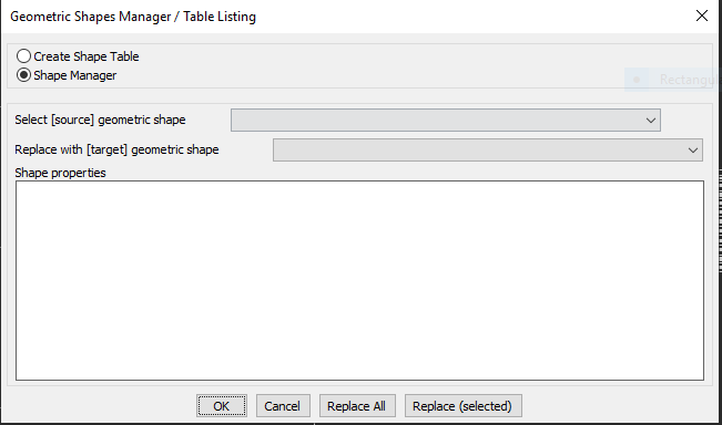
Menu : CADPower -> Miscellaneous -> CAD Procedures -> Second Set -> Shapes Manager
CmdLine : CP_SHAPEMANAGER
The CP_SHAPEMANAGER tool was created in response to requests from the fabrication, sheet cut material handling and architectural practices. The CP_SHAPEMANAGER command is a geometric pattern recognizer and replacement tool. The new functionality added in this update is the ability to create a table of contents of the selected shapes.
The ability to create a table also makes it easy to export the same to Excel as a CSV file. The command identifies geometric shapes, counts them and also optionally allows to replace one shape with another. The program works with closed shapes like circles, ellipses, closed polylines and forms a count list of uniquely shaped & sized objects. You can then replace one shape with another. The replaced shape also must be defined and available in the current drawing.
The CP_SHAPEMANAGER command recognizes standard geometrical shapes like:
Equilateral_Triangle
Isoceles_Triangle
Scalene_Triangle
Round
Square
Rectangle
Irregular_quadrilateral
Pentagon
Irregular_5-sided_polygon
Hexagon
Irregular_6-sided_polygon
Heptagon
Irregular_7-sided_polygon
Octagon
Irregular_8-sided_polygon
Nonagon
Irregular_9-sided_polygon
Decagon
Irregular_10-sided_polygon
Additionally, some standard shapes listed below used in the sheet-metal industry are also recognized:
Obround
Obround-Dimple
Single-D
Double-D
Rectangle_with_corner
Rectangle_with_corner [dimple]
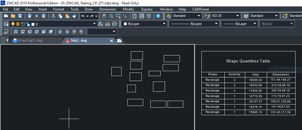
The CP_SHAPEMANAGER command operates in two modes.
In the Shape Manager mode, it replaces one set if shapes with another, as shown in the illustration above. In the ''Create Shape Table' mode, it creates a table of the selected shapes, their count, aree and key dimensions (see example below).
Toolbar : Miscellaneous Tools (CP) 
Menu : CADPower -> Miscellaneous -> CAD Procedures -> Second Set -> Determine the intersection of line and plane
CmdLine : CP_LINEPLANEINT
The CP_LINEPLANEINT command determines the intersection of a point with a plane -or- a line with a plane and marks a point at the intersection.
Toolbar : Miscellaneous Tools (CP) 
Menu : CADPower -> Miscellaneous -> CAD Procedures -> Second Set -> Divide a 3/4 sided polygon
CmdLine : CP_DIVPOLY
The CP_DIVPOLY command divides a triangle or a 4-sided polygon into an equal number of smaller polygons.
Toolbar : Miscellaneous Tools (CP) 
Menu : CADPower -> Miscellaneous -> CAD Procedures -> Second Set -> Join Collinear Lines and Polylines
CmdLine : CP_JOINCOLLINEAR
The CP_JOINCOLLINEAR command is used to join collinear line segments and replace them with one single line. Any extended data or object data contained in the line segments will be transferred to the new line created.
Toolbar : Miscellaneous Tools (CP) 
Menu : CADPower -> Miscellaneous -> CAD Procedures -> Second Set -> Perform drawing audit and cleanup
CmdLine : CP_DWGAUDIT
The CP_DWGAUDIT command is a utility to clean up a drawing of unwanted symbol table information, temporary blocks and also offers a method to flatten the Z values of entities within blocks. Background: Copy-Paste of entities in .dwg CAD can result in a large number of temporary blocks. In AutoCAD, these blocks have names starting with A$ while in BricsCAD the names of these blocks look like E83KJHYTFY and similar hex names.
Toolbar : Miscellaneous Tools (CP) 
Menu : CADPower -> Miscellaneous -> CAD Procedures -> Second Set -> Wipeout buffer around a polygon
CmdLine : CP_WIPEOUT
The CP_WIPEOUT command is useful to create a WIPEOUT mask around a closed polygon by defining a buffer (offset) zone around the polygon.
Toolbar : Miscellaneous Tools (CP) 
Menu : CADPower -> Miscellaneous -> Wblock and preserve AutoCAD Map objects
CmdLine : CP_WBLOCKBC
CP_WBLOCKBC is a command which should be used in BricsCAD when you want to do a WBLOCK (Save Block) on AutoCAD Map drawings containing object data. This is a workaround command to overcome a bug in BricsCAD and prevent losing object data when doing a WBLOCK from BricsCAD on drawings saved in AutoCAD Map.