Polyline Tools
![]() Toolbar : Polyline Tools (CP)
Toolbar : Polyline Tools (CP) 
Menu : CADPower -> Polyline Tools -> Join -> Join 3D Polylines  CmdLine : CP_3DJ
The CP_3DJ command joins 3D segments (lines or polylines) and combines them into a 3D polyline. The PEDIT command does not allow joining of 3D segments. This command fills the need by allowing the Join subcommand to be applied on 3D polyline segments or lines. The segments to be joined must be exactly touching each other.
Once the command has been issued, the prompts that follow are similar to the PEDIT command. You are prompted to select polylines. If a line has been selected, you are prompted to convert it into a polyline. Then you select the objects to join. All touching segments are joined to the first segment resulting in a joined 3D Polyline.
Select 3d polylines/lines to join (or ENTER to select by layer[s]):
Select objects: (do so)
If you are selecting multiple layers for processing, CP_3DJ will join them individually in their respective layers. They will not be joined across different layers except if they are selected explicitly from the command line.
 Toolbar : Polyline Tools (CP)
Menu : CADPower -> Polyline Tools -> Join -> Automated join 2D Polylines CmdLine : CP_PLJOIN
Automatically fuses (joins) all selected line or polyline objects together. The objects should be touching each other at their ends.
Watch: ![]()
Toolbar : Polyline Tools (CP) 
Menu : CADPower -> Polyline Tools -> Join -> Join Conneted Lines/Polylines CmdLine : CP_JOINCONNECTED
Description Pending
Toolbar : Polyline Tools (CP)
Menu : CADPower-> Polyline-> Change 2d->3d->2d-> 2D-to-3D CmdLine : CP_CH2D3D
Converts all the selected 2D Polylines to 3D polylines. A 3D polyline can hold different Z values in each of its vertex. The new 3D polylines thus formed will look exactly like the 2D polylines except that internally they are 3D and therefore can hold Z values.
The standard object selection dialog appears and allows polylines and lines to be selected. Click Apply and all the 2D polylines are converted into 3D polylines. The original 2D polyline will be erased.
Tech Info: CP_CH2D3D changes the DXF Group Code 70 of each polyline, adds the 8 bit and recreates a 3D polyline. The 3D polyline thus created has the 3D flag set. The 3D polyline acquires new handles but any extended entity data in the 2D polyline will be transferred to the 3D polyline.
Watch: ![]()
Toolbar : Polyline Tools (CP) 
Menu : CADPower -> Polyline Tools -> Change 2d->3d->2d -> 3D-to-2D CmdLine : CP_CH3D2D
Converts all selected 3D polylines and lines into 2D polylines and lines. Depending on the setting of the PLINETYPE variable, the 2D polylines thus formed will be either heavy weight polylines or light weight polylines.
While creating the 2d polylines, you can specify the constant elevation that the 2d polylines should acquire.
The following options are possible:
Set to 0.0
Lowest Z of each 3d polyline
Highest Z of each 3d polyline
First vertex elevation
Average of all vertices (default)
The standard object selection dialog appears and allows polylines and lines to be selected.
Click Apply and the all the 3D polylines and lines are converted into 2D polylines. The original 3D polyline will be erased.
Tech Info: CP_CH3D2D changes the DXF Group Code 70 of each polyline, removes the 8 bit and recreates a 2D polyline. The 2D polyline acquires new handles but any extended entity data in the 3D polyline will be transferred to the 2D polyline.
Watch: ![]()
Toolbar : Polyline Tools 
Menu : CADPower-> Polyline-> Vertex Management-> Delete Vertex CmdLine : CP_DELVX
Allows picking a polyline vertex and deleting it in one step. A handy shortcut resulting in much fewer mouse clicks than using the PEDIT EDIT VERTEX NEXT....
Watch: ![]()
Toolbar : Polyline Tools 
Menu : CADPower-> Polyline-> Vertex Management-> Insert Vertex CmdLine : CP_INSVX
Pick any point along a polyline and add a vertex at the picked location. A handy shortcut resulting in much fewer mouse clicks than using the Pedit->Edit Vertex->Next.....
Watch: ![]()
Toolbar : Polyline Tools 
Menu : CADPower -> Polyline Tools -> Vertex Management -> Densify polylines CmdLine : CP_DENSIFY
The CP_DENSIFY command is command can be used to add extra vertices to the polylines, i.e. 2D or 3D based on the "Number of segments" and "Length of segment"
Densify Method
Number of segments: Densifies or adds vertices with specified number of segments.
Length of segment: Densifies or adds vertices with specified length i.e. distance between each vertices.
Watch: ![]()
Toolbar : Polyline Tools 
Menu : CADPower -> Polyline Tools -> Vertex Management -> Weed (remove) collinear vertices from polylines CmdLine : CP_REM_LINVERTS
The CP_REM_LINVERTS command removes vertices which are collinear. Any three vertices which fall in a straight line are said to be collinear and will be be removed.
Mark locations of removed vertices with points: Checking this box marks points at the location where the linear vertices were removed.
Watch: ![]()
Toolbar : Polyline Tools 
Menu : CADPower -> Polyline Tools -> Vertex Management -> Place points or blocks along polyline vertices CmdLine : CP_PL_PLACE
This command places a point or a block at each vertex of a polyline/line. Useful for many mapping and utility applications.
What to place?:
Points: Choosing this option allows to place points on vertices of Pline/Line. On specified layer.
Blocks: Choosing this option allows to place block on vertices of Pline/Line. On specified layer.
Block Name: Clicking on the button "Block Name" allows to select the block for insertion.
(Note: You can select one block at a time)
Insertion Settings:
Scale Factor: Allows to enter the required scale factor for the block.
Rotation Angle: Allows to enter the required rotation angle for the block.
Which layer to place?:
Source: Choosing this option places the block/point in source object layer.
Current: Choosing this option places the block/point in current layer.
Toolbar : Polyline Tools 
Menu : CADPower -> Polyline Tools -> Vertex Management-> Add/Remove redundant closing vertex in polyline CmdLine : CP_FIXCLOSED
The CP_FIXCLOSED command helps to add or remove the redundant last vertex of a closed polyline. In other words, this command adds or removes the duplication of the last vertex in closed polylines, which may sometimes be desirable and sometimes not.
Add Closing Vertex
Adds a redundant "last" vertex to closed polylines. This duplicates the first and last vertex of a closed polyline. The new vertex is added only if the distance between the first and last vertex is greater than the closing tolerance specified in the dialog box above.
Remove Closing Vertex
Removes the last vertex from the polyline if the distance between the first and last vertex is less than the value specified in the dialog box above.s
Toolbar : Polyline Tools 
Menu : CADPower -> Polyline Tools -> Vertex Management -> Delete single vertex polylines CmdLine : CP_DELSVP
The CP_DELSVP command deletes a single vertex or zero-length polyline from the selected objects. Unlike the CP_0LEN2PNT command which creates a point at every location of a zero-length polyline, this command will delete it from the drawing.
Toolbar : Polyline Tools ![]()
Menu : CADPower-> Polyline-> Vertex Management-> Multiple Vertex Editor CmdLine : CP_MVEDIT
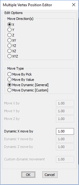
The CP_MVEDIT command is used to edit multiple vertex positions from multiple selected polylines, lines and arcs.
With the CP_MVEDIT command, you can move multiple vertices from many objects at once in the X, Y, Z, XY, YZ, XZ or XYZ directions while keeping the other coordinate unchanged. Think of this as a tool similar to the XYZ point filters in AutoCAD and BricsCAD, but applied across multiple objects and multiple selected points of a polyline, line or arc.
The CP_MVEDIT command was originally intended to provide basic vertex editing tools based on fixed X, Y and Z movements. In V 17.01, we extended the functionality by adding simple dynamic movements which allowed interactive movement on the screen while the user could see the results graphically.
In this update, we have further enhanced it and this tool can now be used for several size, area and proximity simulation studies.
A new option called 'DynamicCustom' which was added in V 17.01 has been further improved.
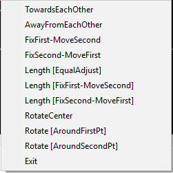
The following options are now available in this command:
- TowardsEachOther (moves both picked vertices towards each other)
- AwayFromEachOther (moves both picked vertices away from each other)
- FixFirst-MoveSecond (keeps first point fixed and moves the second point away)
- FixSecond-MoveFirst (keeps second point fixed and moves the first point away)
- Length [EqualAdjust] (adjusts length by moving both points either towards or away from each other)
- Length [FixFirst-MoveSecond] (adjusts length by keeping first point fixed and second point away from first)
- Length [FixSecond-MoveFirst] (adjusts length by keeping second point fixed and first point away from second)
- RotateCenter (rotate around the center, the segment formed by two points)
- Rotate [AroundFirstPt] (rotate the 2-point segment around the first point) - WIP
- Rotate [AroundSecondPt] (rotate the 2-point segment around the second point) - WIP
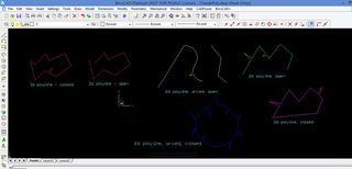
The basic editing premise is that you pick two points on the polyline to edit, and apply an editing operation as described above.
The editing operations are based on relative movements, with directional constraints applied. Each iteration of the movement results in a new shape of the polyline which changes the area as well as perimeter. This is shown on the screen interactively so that you can stop the simulation when the desired results are achieved. There is also a 'Reverse' option provided which can be used to quickly reverse the simulation direction. This is useful when you are near the intended final result but need to go back and forth to get the perfect geometry.
Toolbar : Polyline Tools 
Menu : CADPower -> Polyline Tools -> Vertex Management -> Specify a new start point for closed polylines CmdLine : CP_NEWSTART
The CP_NEWSTART command allows to specify a new start point for closed polylines. Use this to change the start point of closed polylines without changing the polyline geometry. The new point specified must fall on the polyline and the nearest vertex is taken as the start point and the polyline is re-constructed
Watch: ![]()
Toolbar : Polyline Tools 
Menu : CADPower -> Polyline Tools -> Vertex Management -> Tweak polyline vertex CmdLine : CP_TWEAKPOLY
CP_TWEAKPOLY command is usedl to tweak, tweeze or pinch out a vertex from the polyline. The CP_TWEAKPOLY command extracts a new vertex, pulled out from the polyline, unlike grip-editing which allows you to move existing ones.
The pictures below will make is clear what this command does.
The many shades of CP_TWEAKPOLY in operation.
Watch: ![]()
Toolbar : Polyline Tools 
Menu : CADPower -> Polyline Tools -> Part Editing -> Extract part of polyline CmdLine : CP_PARTEXTRACT
The CP_PARTEXTRACT command is useful to extract part of a polyline. You will be asked to pick two points that fall on the polyline and all the segments in between the two picked points will be extracted and a new polyline will be created on the current layer.
Note: Polylines which have been curve fit using the Fit or Spline option cannot be used by this command. If there are arc segments in the polyline, they will be replaced with their straight line joins.
Watch: ![]()
Toolbar : Polyline Tools 
Menu : CADPower-> Polyline-> Part Editing-> Move part of polyline CmdLine : CP_PARTCOPY
The CP_PARTCOPY command is useful to copy a part of a polyline. You will be asked to pick two points that fall on the polyline and a polyline will be created between these two points and you will be asked to move this polyline and place it at a new location.
Note: Polylines which have been curve fit using the Fit or Spline option cannot be used by this command. If there are arc segments in the polyline, they will be replaced with their straight line joins.
Toolbar : Polyline Tools 
Menu : CADPower -> Polyline Tools -> Part Editing -> Offset part of polyline CmdLine : CP_PARTOFFSET
The CP_PARTOFFSET command is useful to offset part of a polyline. You will be asked to pick two points that fall on the polyline and all the segments in between the two picked points will be offset using the standard AutoCAD OFFSET command.
Note:
1) Polylines which have been curve fit using the Fit or Spline option cannot be used by this command.
2) If there are arc segments in the polyline, they will be replaced with straight line segments.
Toolbar : Polyline Tools 
Menu : CADPower -> Polyline Tools -> Part Editing -> Stretch part of polyline CmdLine : CP_PARTSTRETCH
The CP_PARTSTRETCH command is useful to stretch a portion of a polyline. You will be asked to pick two points that fall on the polyline and all the segments in between the two picked points will be stretched to a new location. Once the new polyline is created a line is drawn connecting the stretched and un-stretched portions of the polyline.
Note: Polylines which have been curve fit using the Fit or Spline option cannot be used by this command. If there are arc segments in the polyline, they will be replaced with their straight line joins.
Toolbar : Polyline Tools 
Menu : CADPower -> Polyline Tools -> Part Editing -> Mirror part of polyline CmdLine : CP_PARTMIRROR
The CP_PARTMIRROR command is useful to mirror only a portion of a polyline. You will be asked to pick two points that fall on the polyline and all the segments in between the two picked points will be flipped (mirrored) with the two picked points as the axis of mirroring. The polyline is updated with the new geometry and retains its handle, Xdata etc.
Note: Polylines which have been curve fit using the Fit or Spline option cannot be used by this command. If there are arc segments in the polyline, they will be replaced with their straight line joins.
Toolbar : Polyline Tools 
Menu : CADPower -> Polyline Tools -> Part Editing -> Rotate part of polyline CmdLine : CP_PARTROTATE
The CP_PARTROTATE command is useful to rotate only a portion of a polyline. You will be asked to pick two points that fall on the polyline and all the segments in between the two picked points will be rotated using the first point as the base point. The polyline is updated with the new geometry and retains its handle, Xdata etc.
Note: Polylines which have been curve fit using the Fit or Spline option cannot be used by this command. If there are arc segments in the polyline, they will be replaced with their straight line joins.
Toolbar : Polyline Tools 
Menu : CADPower -> Polyline Tools -> Part Editing -> Reshape part of polyline CmdLine : CP_PARTRESHAPE
The CP_PARTRESHAPE command can be used to re-shape or, in other words, re-digitize part of a polyline. You will be asked to pick two points on a polyline and will be prompted to pick the new locations of the points in between. The source polyline will then be updated and the newly digitized points will be used instead of the old set of points between the two source points.
Toolbar : Polyline Tools 
Menu : CADPower-> Polyline Tools -> Inquiry Statistics -> Compute detailed polyline statistics CmdLine : CP_PL_STAT
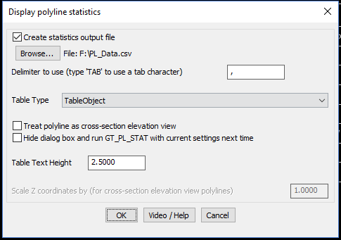
The CP_PL_STAT command generates detailed statistics from a selected polyline. The statistics is resported in three different areas:
- On the command line

- As a CAD Table
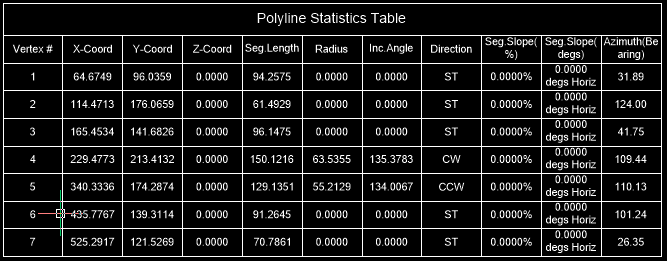
- As CSV files whch can be opened in Excel.
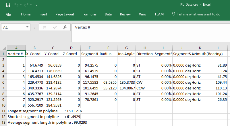
Create output file: Check this option if you want the output from this command to be exported to CSV file which is the native format for Excel.
The contents of the CSV file has been expanded to include the following:
Vertex #,X-Coord,Y-Coord,Z-Coord,SegmentLength,Radius,Inc.Angle,Direction,SegmentSlope(%),SegmentSlope(degs),Azimuth(Bearing)
Browse: Click on this button to select an output file to save the polyline statistics listing
Create tabular output: Creates the polyline statistics in a tabulated form
Table Type: Choose the table type here. The options are CAD Table, Text Table or None.
Treat polyline as elevation view: Checking this option causes the polyline to be treated as elevation view. In other words, the X and Y of the two vertices of the polyline are treated as measurements in the Z plane and the difference between the Y values is taken as the actual elevation difference between the points.
Hide dialog box and run CP_PL_STAT with current settings next time: Checking this option causes CP_PL_STAT to run the next time without dialog box. You will be prompted to only select the polyline to compute statistics and the program operates with the current settings as last set. This setting enables users to run the command quickly without having to navigate through the dialog box each time. The setting remains in place for the current CAD session unless it is reset using the CP_SHOWDLG command.
Table Text Height: Specify the required text height for the contents of table.
Watch: ![]()
![]()
Toolbar : Polyline Tools 
Menu : CADPower -> Polyline Tools -> Inquiry Statistics -> Compute summed polyline areas from selected layers CmdLine : CP_LAYERAREA
The CP_LAYERAREA command displays the total summed area and length of all polylines in selected layer(s).
Select layers: Clicking on this button displays the complete list of layers in the drawing. From this list, you can select the layers for which you want the total summed areas to be displayed and these will be displayed each time the command starts.
Create table of layers areas: Checking this box generates a table of Area, Length and Color of selected layers as shown below.
Toolbar : Polyline Tools 
Menu : CADPower-> Polyline-> Inquiry Statistics-> Compute Lengths CmdLine : CP_LENGTH
Adds up the lengths of selected lines, polylines, splines, circles and arcs. Displays both horizontally projected length and actual slope length where applicable.
Toolbar : Polyline Tools 
Menu : CADPower-> Polyline-> Inquiry Statistics-> Compute summed areas of closed polylines CmdLine : CP_CALCAREA
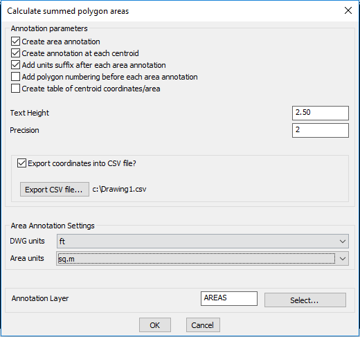
The CP_CALCAREA command sums up the areas of all closed polylines, splines and circles. The area report uses the current unit settings as set in the Area Annotation Settings (see below). The area can also be annotated at the centroidal locations in the form of text objects.
Annotation parameters:
Create area annotation: This option enables creation of area annotation text.
Create annotation at each centroid: This option creates each polyline area annotation at its individual centroid position.
Add units suffix after each area annotation: This option adds the area suffix at the end of each annotation in the drawing. The suffix is never added in the table as well as in the CSV export.
Add Polygon numbering before each annotation: This option creates a polygon numbering before each area annotation. The polygon numbering starts from 1 and is placed in brackets thus (1)
Create table of centroid coordinates/area: This option creates a table of the centroid coordinates (X, Y, Z), the area and the point number.
Text Height: Specify the text height here.
Precision: Specify the decimal precision to be used for the coordinates and the area annotation.
Export coordinates to CSV file: Checking this option creates a CSV export.
Area Annotation parameters:
DWG units: Specify the drawing units here. The options available are mm, cm, in, meters and yards.
Area Units: Specify the units in which the area must be reported. Available options are dwg, sq.mm, sq.cm, sq.in, sq.ft, sq.m, sq.yards, acres, hectares, sq.km, sq.mi, cents and kattah.
Annotation Layer: Specify the layer in which the annotation is to be created.
Toolbar : Polyline Tools 
Menu : CADPower-> Polyline-> Inquiry Statistics-> Display info. about polyline bulge (arc segments) CmdLine : CP_BULGE
Polylines that have arc segments in them and those which are curved fitted use bulge value to represent their curvature. These bulge values are stored in the polyline object itself. The CP_BULGE command helps to print out the bulge values at each of the vertex. This can be useful in various debugging situations.
Command: bulge
Select a polyline:
Bulge at vertex 1 is 0.0894 and Radius is 324.302
Bulge at vertex 2 is 0.1412 and Radius is 133.308
Bulge at vertex 3 is 0.0910 and Radius is 262.438
Bulge at vertex 4 is -0.0778 and Radius is 356.879
Bulge at vertex 5 is -0.0477 and Radius is 448.144
Bulge at vertex 6 is -0.0398 and Radius is 642.951
The CP_BULGE command creates POINT objects at each bulge location, in a temporary layer.
Toolbar : Polyline Tools ![]()
Menu : CADPower -> Polyline Tools -> Inquiry Statistics -> Search entities via handles CmdLine : CP_FINDHND
Description Pending
Toolbar : Polyline Tools ![]()
Menu : CADPower -> Polyline Tools -> Inquiry Statistics -> Measure distance between two points on curve CmdLine : CP_MEASURE2POINTS
Description Pending
Watch: ![]()
Toolbar : Polyline Tools 
Menu : CADPower -> Polyline Tools -> More Editing -> Express PEDIT CmdLine : CP_XV
Express Pedit allows a faster and quicker way to access some of the Pedit Edit Vertex commands like Move, Insert and Break. Additionally, it also provides extra commands like polyline statistics - slope length, horizontal projected length, X, Y and Z coordinate extents and number of vertices.
Select vertex on polyline:
Next / Previous / Move / Z / Insert / Break / Statistics / Settings / eXit <Next>:
Use Next and Previous to navigate through the vertices of the polyline. The current vertex is always shown with a cross attached to it.
Move allows specifying a new location for the current vertex.
Z allows the elevation of the current point to be set
Insert allows a new vertex to be added between the current vertex and the next vertex.
Break allows the polyline to be broken at the current point. Saves some keystrokes as compared to the Pedit command.
Statistics: Generates detailed polyline statistics
Settings allows specifying whether the Move and Insert sub-commands take the Z value from the new location or inherit it from the current vertex elevation.
An example of the statistical information is shown below:
Slope length:22719.1175 Projected horizontal length:22718.4936
Max. X-coordinate:2025286.6092 Min. X-coordinate:2010210.0148
Max. Y-coordinate:924910.0082 Min. Y-coordinate:913590.4827
Max. Z-coordinate:212.5000 Min. Z-coordinate:45.6000
Number of vertices:15
Press any key to continue.
Tech Info: Make sure that the entire polyline is visible on screen.
Toolbar : Polyline Tools 
Menu : CADPower -> Polyline Tools -> More Editing -> Multiple PEDIT CmdLine : CP_MPEDIT
This is a global Pedit command applied to multiple polylines. The PEDIT command operates on one polyline at a time. CP_MPEDIT can be used to select multiple polylines and process them. It offers the following commands: Open, Close, Fit, Spline, Decurve, Convert to polylines and Change Widths etc.
If the Convert to polylines option is chosen, CP_MPEDIT will allow selection of lines, arcs and circles as input data.
If Change Width option is chosen, CP_MPEDIT will allow selection of polylines, lines, arcs and circles as input data.
Toolbar : Polyline Tools 
Menu : CADPower -> Polyline Tools -> More Editing -> Change widths CmdLine : CP_CHW
The CP_CHW command is useful to change the widths of selected lines, polylines, arcs or circles. Non-polyline objects will be converted to polylines.
Specify the width to set in the width-control dialog box and select the objects to process through the object selection dialog box.
Toolbar : Polyline Tools 
Menu : CADPower-> Polyline-> More Editing-> Explode polylines with width CmdLine : CP_XP_WPL
The CP_XP_WPL command allows Linear polylines with widths to be exploded and to retain the geometry of the original polyline. The exploded objects will be created as lines.
Layer to place
Source: Explodes the polyline and places the result in the layer in which it was created (source layer)
Current: Explodes the polyline and places the result in the layer which is current
Specify: Explodes the polyline and places the result in the layer selected by the user
Layer-name: Displays the name of the layer selected
Select: Clicking on Select button pops up the select layer dialog box
Delete original objects: Checking this box deletes the original source object after exploding
Toolbar : Polyline Tools 
Menu : CADPower -> Polyline Tools -> More Editing -> Specify segment lengths in polylines CmdLine : CP_SEGLENSET
The CP_SEGLENSET command is used to specify a new segment length for each of the segments of the polyline. The command will highlight each segment of the polyline one by one in red color and ask for a new segment length. On entering the new length, the polyline is updated such that the segment gets the specified length.
Toolbar : Polyline Tools 
Menu : CADPower -> Polyline Tools -> More Editing -> Delete segment from polyline CmdLine : CP_SEGDEL
The CP_SEGDEL command is used for deleting one or more than one segment from polyline.
Watch: ![]()
Toolbar : Polyline Tools
Menu : CADPower -> Polyline Tools -> More Editing -> Align polyline edges CmdLine : CP_ALIGNPOLY
The CP_ALIGNPOLY command is used for align one polyline with another based on its edge.
Toolbar : Polyline Tools 
Menu : CADPower -> Polyline Tools -> Flip -> Flip (Reverse) direction CmdLine : CP_FLIP
Reverses the direction of the polyline vertices. This command preserves the handle (see below for conditions) as well as any extended entity data that is stored with the polyline or with each or any of its vertices (in case of heavy weight polylines).
Direction Control:
Clockwise:
Choosing this option flips all counter-clockwise polylines to clockwise
CounterClockwise:
Choosing this option flips all clockwise polylines counter-clockwise
Interchange: Reverses the direction of all selected polylines irrespective of whether they are clockwise or counterclockwise.
Low to High Z:
Reverses the direction of the polylines whose last vertex elevation (Z value) is higher than the first vertex elevation (Z value).
High to Low Z:
Reverses the direction of the polylines whose last vertex elevation (Z value) is lower than the first vertex elevation (Z value).
Display graphically:
Displays the polyline direction graphically by drawing leader arrows along the polyline segments. Does not slip the polyline.
Retain same object handle for reversed polylines:
Choosing this option ensures that the reversed polylines have the same handle as the original polyline. This takes longer time to process and it does not work on polylines having arc segments. The object handle is always preserved for 3d polylines irrespective of whether the option above is chosen or not. In case of 2D polylines, the object handles will not be preserved unless this option is set. Switching this option off can greatly improve the process speed especially for long polylines.
Hide dialog box and run CP_FLIP with current settings:
By clicking this option, you can run CP_FLIP any number of times in the current session without the dialog box. You will be prompted to only select the polylines to flip and the program operates with the settings last set. The setting remains in place for the current CAD session unless it is reset using the CP_SHOWDLG command.
Tech Info: The extended entity data in the objects will always be retained.
Watch: ![]()
Toolbar : Polyline Tools 
Menu : CADPower-> Polyline-> Flip-> Flip (Mirror) arc segments of polyline CmdLine : CP_PLARCMIRROR
The CP_PLARCMIRROR command flips (mirrors) ONLY the arc segments of a polyline with arcs. This can be a useful tool to flip the direction of polyline arcs in many mapping situations where arced polylines are used to show vegetaion symbols. In particular, this command may be used to fix the polyline arc direction if it has been generated incorrectly by the CP_VEGLINE command in CADPower.
Watch: ![]()
Toolbar : Polyline Tools 
Menu : CADPower -> Polyline Tools -> Fillet -> Enhanced fillet command CmdLine : CP_FILLETPOLY
The CP_FILLETPOLY command allows filleting to be done between two polylines. The two segments of the polyline nearest to the ends picked will be filletted according to the specified radius.
The command is now offered as a replacement for the standard fillet command, which has several short-comings. For example, the AutoCAD/BricsCAD fillet command does not work correctly under the following situations:
a. Fillet between an ARC and a polyline object
b. Fillet between a LINE and polyline that has arc segments near the fillet end.
c. Fillet between an ARC and polyline that has arc segments near the fillet end.
The CP_FILLETPOLY command processes all of the cases in (a), (b) and (c) above successfully.
Fillet Radius: Specify the radius to be applied for filleting across all the segments of the multiple selected polylines.
Command: filletpoly
Select first polyline: <do so>
Select second polyline: <do so>
Toolbar : Polyline Tools 
Menu : CADPower -> Polyline Tools -> Fillet -> Fillet multiple polylines CmdLine : CP_MFILLET
The CP_MFILLET command allows multiple polylines to be filleted at once with the Fillet Polyline option.
Fillet Radius: Specify the radius to be applied for filleting across all the segments of the multiple selected polylines.
Toolbar : Polyline Tools 
Menu : CADPower -> Polyline Tools -> Others -> Offset closed polylines Inwards/Outwards CmdLine : CP_INOUTOFFSET
The CP_INOUTOFFSET allows multiple closed polylines to be offsetted INwards or OUTwards with one single command.
Command: CP_INOUTOFFSET
Select Objects: (select polylines to offset)
Offset direction: [ Inwards/Outwards ] <Outwards>: (Type Inwards or Outwards)
Horizontal offset distance : <1.0000>: (Enter horizontal distance to offset)
Watch: ![]()
Toolbar : Polyline Tools 
Menu : CADPower -> Polyline Tools -> Others -> Explode Splined CmdLine : CP_XPSPL
This command is used to explode splined and fitted polylines. Upon selecting the splined or fitted polylines, they are exploded into their line or arc segment and then joined back to produce a "plain" polyline with line or arc segments. This command is useful to many geographic and surveying users who require a non-splined non-fitted polyline for many design purposes.
Toolbar : Polyline Tools 
Menu : CADPower-> Polyline-> Others-> Control polyline linetypes CmdLine : CP_FLOW_LT
In AutoCAD / BricsCAD , polylines can be set with a flag to determine if flowing linetypes are enabled or not. When flowing linetypes are enabled, the linetype pattern and scale are applied continuously across even small length segments thereby generating the linetype correctly. If this flag is disabled, the linetype pattern is applied each time at the start of a new segment. This may cause improper representation of the linetype in a polyline with very short segments. This command provides a means to set or remove flowing linetypes from selected polylines.
Toolbar : Polyline Tools 
Menu : CADPower-> Polyline-> Others-> Zoom to polyline CmdLine : CP_ZPOLY
Pick a polyline and zoom to the lower left and upper right extents.
Toolbar : Polyline Tools 
Menu : CADPower -> Polyline Tools -> Others -> Fix lines/polylines with different UCS CmdLine : CP_FIXUCS
The CP_FIXUCS command allows entities which have been created or placed in a different non-parallel UCS to be brought back to the WCS. All efforts are made to reposition entities at the same physical position as before. However, it is possible that some entities may not always map back correctly. Use your judgement and discretion to accept the results of this tool. Currently, lines, polylines and text objects are supported and can be tranformed from UCS to WCS..
Layer to place
Source: Creates the new polyline and places it in the layer in which it was created (source layer)
Current: Creates the new polyline and places it in the current layer
Specify: Creates the new polyline and places it in the layer specified by the user
Layer-name: Displays the name of the layer selected
Select: Clicking on Select button pops up the select layer dialog box
Delete original objects: Checking this box deletes the original source object
Watch: ![]()
Toolbar : Polyline Tools 
Menu : CADPower -> Polyline Tools -> Others -> Draw linear polylines from arced polylines CmdLine : CP_LINPOLY
The CP_LINPOLY command is used to create a linear polyline from an arced polyline. It creates a polyline by joining each vertex of the arced polyline with a straight line. The arced section is thus replaced with a straight line (arc-chord). The CP_LINPOLY command has an option to run without the dialog box selector.
Toolbar : Polyline Tools 
Menu : CADPower -> Polyline Tools -> Others -> Acquire Neighboring polyline elevations CmdLine : CP_POLYGETZ
CP_POLYGETZ command can be used to perform elevation transfer operations from one polyline [target] to another [source] based on specific criteria.
When you start this command, you are asked to select a source and target polyline. Once this is done, you get a dialog box as shown, specify the required Search Tolerance and choose the required operation.
Create a vertex on source polyline nearest to each vertex on target polyline:
In this method, for each vertex of the target polyline, a 3D point nearest to it on the source polyline is determined. The source polyline is then replaced with a new polyine created using all such points which are essentially the nearest points (on the source polyline) of vertices of the target polyline. Therefore, this method results in the source polyline having exactly the same number of points as the target polyline but in the XY region of the nearest point on source polyline and the elevations belonging to the nearest target polyline vertex.
Populate existing source polyline vertex elevations from nearest point on target polyline:
In this method, each vertex elevation of the source polyline is replaced with the elevation of a point on the target polyline which happens to be the nearest point to it [the source polyline vertex]. In other words, this will result in the number of vertices of the source polyline to be the same but its elevation can change based on the target polyline elevations.
Watch: ![]()