Annotation Tools
 Toolbar : Annotation Tools
Menu : GeoTools -> Annotation -> Label polyline vertices  CmdLine : GT_VXLABEL
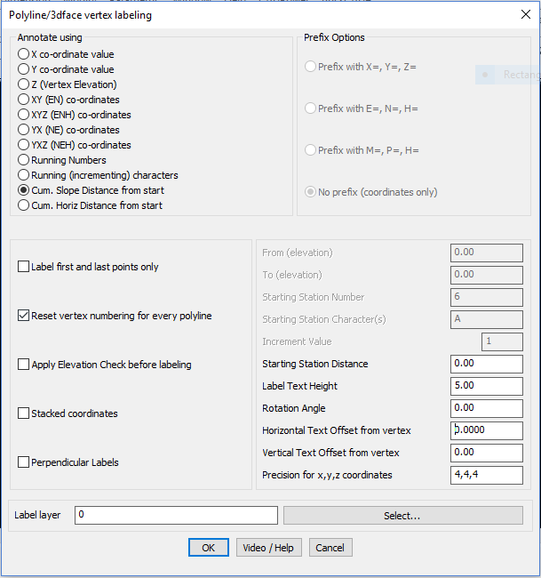
This command places text labels along polyline, line, 3dfaces and spline vertices. The following types of labels can be created for each vertex.
Annotate Using:
X co-ordinate value:
The X co-ordinate of each vertex is written as a text label next to each vertex.
Y co-ordinate value:
The Y co-ordinate of each vertex is written as a text label next to each vertex.
Elevations (Z):
The elevation of each vertex is written as a text next to each vertex.
XY co-ordinate value:
The x and y co-ordinates of each vertex is written as a text label next to each vertex.
XYZ co-ordinate value:
The x, y and z co-ordinates of each vertex is written as a text label next to each vertex.
Running Number:
The vertex count starting from the beginning is written (this initial count can be set by the user)
Cumulative Slope Distance from start:
The cumulative slope distance from the first vertex is computed and written next to each vertex (the initial starting distance can be set by the user).
Cumulative Horizontal Distance from start:
The cumulative horizontal distance from the first vertex is computed and written next to each vertex (the initial starting distance can be set by the user).
Prefix Options:
Prefix with X=, Y=, Z= Choosing this option places the prefixes, X=, Y=, Z= before each coordinate value
Prefix with E=, N=, H= Choosing this option places the prefixes, E=, N=, H= before each coordinate value
No prefix (co-cordinates only) No prefixes are written, only co-ordinates values are written
Prefix with M=, P=, H= Choosing this option places the prefixes, M=, P=, H= before each coordinate value. This is Portuguese notation for Easting and Northing.
Label first and last points only:
Places labels on the first and last points of polylines only. Useful if the polyline is too dense and you do not want lables at every point.
Reset vertex numbering for every line/polyline:
Starts vertex numbering from the specified start value for every polyline or line. If this option is not checked, vertex numbering continues incrementing across each polyline.
Apply elevation check before labeling.
Checking this box makes a check for the elevation between specified range and labels only those vertices which fall between the range
From [elevation]
If Apply elevation check before labeling is chosen then the From [elevation] box allows you to enter the start elevation for range check.
To [elevation]
If Apply elevation check before labeling is chosen then the To [elevation] box allows you to enter the end elevation for range check.
Starting Station Number:
If Running Number is chosen as the label option above, then this option allows the first station number to be set. You may want to set this to a number higher than 1 if this polyline is being labeled in succession to another polyline which was preceding it.
Starting Station Distance:
If Cumulative Distance from start is chosen as the label option above, then this option allows the first station distance to be set. You may want to set this to a number higher than 0.0 if this polyline is being labeled in succession to another polyline which was preceding it.
Label Text Height:
Specifies the label text height.
Rotation Angle:
Specifies the rotation angle for text.
Horizontal Text Offset from vertex:
Specifies the offset distance in the horizontal (X) direction in CAD units from the vertex position at which you want the label to appear.
Vertical Text Offset from vertex:
Specifies the offset distance in the vertical (Y) direction in CAD units from the vertex position at which you want the label to appear.
Precision for x,y,z coordinates:
Specifies the X, Y and Z coordinates precision independently. They must be separated by commas. For example, entering the coordinates
precision as 2,2,1 will display the coordinates with 2 decimal places in X, 2 in Y and 1 in Z.
Label-name: Displays the selected layer name.
Select: Pops-up the Select Label Layer dialog box for choosing the required layer.
Watch: ![]()
Toolbar : Annotation Tools 
Menu : GeoTools -> Annotation -> Label polylines with attached data CmdLine : GT_PL_DATALBL
The GT_PL_DATALBL command is used to label polylines with attached data – like object data, extended entity data or database-linked data. When multiple object labeling is chosen, the label is automatically placed at the mid-point of each object. When single object labeling is chosen, the user has to specify the label locations. You can create complex label strings by joining data from multiple fields with a specified delimiter, with prefix/suffix etc as required.
The command offers several sub-dialogs which allow individual categorized parameters (OD / DB / XD) and general settings to be specified.
Annotation parameters:
The annotation parameters specify the visual appearance of the annotation and are common to all the three data types being annotated.
Style: This button brings up the annotation style dialog box that determines how the text label annotation is to be placed relative to the polyline and view direction
Object Data settings dialog:
Database settings dialog:
Annotation Style settings dialog:
Data Format: This button brings up the Data Format dialog box that specifies various miscellaneous formatting options as shown below.
Toolbar : Annotation Tools 
Menu : GeoTools -> Annotation -> Label polyline segments CmdLine : GT_SEGLABEL
This command writes the segment distance annotation along each segment of the polyline.
What to label?
Distances: Choosing this option places the inter-vertex distance as the label text.
Bearing: Choosing this option places the surveyor’s bearing between two vertices as the label text.
Slope: Choosing this option places the segment slope annotation as the label text.
Distances@Slope: Choosing this option creates the annotation in the format - ‘Distance @ Slope'
Distances@Bearing: Choosing this option creates the annotation in the format 'Distance @ Bearing'
Running Number: Choosing this option allows to label the segments as sequential numbers
Labelling Formats:
Distances: Clicking this option opens up a distances format dialog box. This allows the distances to be annotated in various ways.
Slope: Displays distances as actual slope distances.
Horizontal: Displays distances as horizontally projected values.
Apply Segment length check before labeling: Checks the length of the segment and if it falls within the specified range only, they will be labelled.
Bearing: Clicking this option opens up a bearing format dialog box. This allows the bearings to be annotated in various ways.
Decimal Degrees: Writes the whole circle bearing in decimal degrees.
Deg/Min/Sec (000-00-00): Writes the bearing in degrees, minutes and seconds in the DDD-MM-SS format.
0d00'00': Writes the whole circle bearing in deg, min and sec format.
0º00'00": degree-minute-second format in the style D°M'S".
N 0d00'00' E: Writes the bearing in surveyors units.
Radians: (0.000r) Writes the whole circle bearing in radians
Gradients: (0.000g) Writes the whole circle bearing in gradients (One gradient=1/400th of a circle)
Slope: Clicking this option, opens up a slope format dialog box. This allows the slopes to be annotated in various ways
As percentage: Choosing this option causes the grade annotation to be created as a percentage. For example, uphill grades are created as "2% Up" and downhill grades are created as "2% Down".
As decimal: Choosing this option causes the grade annotation to be created in decimal format. For example, uphill grade will be created as "1:50 Up" and downhill grade will be created as "1:50 Down".
Direction: Choosing this option causes the strings "Up" or "Down" to be written along the segment depending on whether the slope is going downward or upward.
Arrow in Elevation Direction [Up->Down]: Choosing this option draws an arrow along the segment in Upward to Downward direction with respect to the elevation.
Arrow in Elevation Direction [Down->Up]: Choosing this option draws an arrow along the segment in Downward to Upward direction with respect to the elevation.
Degrees: Choosing this option causes the slope values in degrees to be annotated next to the segment.
Per Mille: mean 'Per 1000' : This slope annotation method is often used in hydraulics to denote the slopes of canal beds and similar structures. It is
denoted as 'x o/oo', where 'x' is the amount of slope per 1000 of horizontal distance.
Precision for grade value: Enter the number of decimal places to be used in the precision for grade values.
Treat polyline as elevation value: If this option is checked, the polyline is treated as an elevation view (or long/cross section as called in some countries) and the segment slope annotation is done accordingly. In elevation view, the polyline is assumed to be drawn in the Z plane.
Vertical exaggeration factor: This is the factor by which the Z value of the polyline vertices must be multiplied when the polyline is being viewed
in 'ElevationView'.
Annotation Position:
Along Segment: Choosing this option places the annotation text along the direction of the segment.
Perpendicular to segment: Choosing this option places the annotation text perpendicular to the direction of the segment being annotated.
The next two options further specify the annotation text placement positions by specifying if the annotation is along the segment, above or below it. For Perpendicular to segment option above, The Above, Below and On Segment option in this section will be grayed out.
Above Segment: The annotation will be placed above the segment. For the purpose of determining the position of anotation, the segment is imagined from its start point to end point as a horizontal X-axis, and the the space above it is considered as the Space Above and vice versa.
Below Segment: The annotation will be placed below the segment. For the purpose of of determining the position of annotation, the segment is imagined from it start point to end point as a horizontal X-axis, and the space below it is considered as the Space Below and vice versa.
On Segment: The annotation will be placed on and along the segment.
Left of segment: This option enables the annotation to be placed to the left of the direction of the segment being annotated. This is applicable only when the Perpendicular option is chosen.
Right of segment: This option enables the annotation to be placed to the right of the direction of the segment being annotated. This is applicable only when the Perpendicular option is chosen.
Text Orientation:
Always upright: Flips text by 180 degrees to make them readable.
Always aligned: Does not perform any text flipping. The rotation angle will be as determined, entirely by the segment direction.
ARC label options:
Midpoint of arc: Choosing this option places the label at the midpoint of each arc segment. This may be an arc segment of a polyline or an ARC object.
Midpoint of chord: Choosing this option places the label at the midpoint of each chord length of the arc segment. This may be an arc segment of a polyline or an ARC object.
Label Formatting:
Label Text Height: Specifies the label text height.
Watch: ![]()
Toolbar : Annotation Tools 
Menu : GeoTools -> Annotation -> Label contour polylines CmdLine : GT_CONTLABEL
The GT_CONTLABEL command places labels along polylines, lines, arcs and splines. You can use it to label just about anything that is a linear object such as label roads, fences, boundaries, traversas, etc. The label can be the elevation of the object or you can specify a user string to be placed as a label.
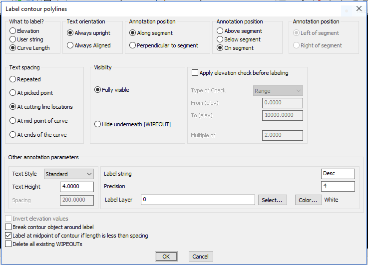
What to label?
Elevation: Labels the elevation information of the polyline
User String: Enter a user-defined string value that is used to annotate along the polyline.
Curve Length: Labels the length of contour.
Text Orientation
Always upright: Create labels that are always face up. This cause any text that is between rotation angles of 90 and 270 degrees to be flipped by 180 degrees.
Always aligned: Check this option to create labels which are always aligned to the direction of the line. This can result in inverted text.
Annotation Position:
Along Segment: Choosing this option places the annotation text along the direction of the contour segment.
Perpendicular to segment: Choosing this option places the annotation text perpendicular to the direction of the segment being annotated.
The next two options further specify the annotation text placement positions by specifying if the annotation is along the segment, above or below it. For Perpendicular to segment option above, The Above, Below and On Segment option in this section will be grayed out.
Annotation Position:
Above Segment: The annotation will be placed above the segment. For the purpose of determining the position of anotation, the segment is imagined from its start point to end point as a horizontal X-axis, and the the space above it (positive Y axis) is considered as Above.
Below Segment: The annotation will be placed below the segment. For the purpose of determining the position of anotation, the segment is imagined from its start point to end point as a horizontal X-axis, and the the space below it (negative Y axis) is considered as Below.
On Segment: The annotation will be placed on and along the segment.
Annotation Position:
Left of segment: This option enables the annotation to be placed to the left of the direction of the segment being annotated. This is applicable only when the Perpendicular option is chosen.
Right of segment: This option enables the annotation to be placed to the right of the direction of the segment being annotated. This is applicable only when the Perpendicular option is chosen.
Text spacing
Repeated: Checking this option causes GT_CONTLABEL to place the labels repeatedly along the line at an interval specified in the Spacing (see below)
At picked point: Checking this option allows the user to manually pick points on the line where the annotation is desired. This option does not place annotations automatically and does so only at the picked point.
At cutting line locations: Checking this option allows the user to specify two points that define a line and the program will generate annotations at every intersection of the line with the selected contour polyline objects.
At mid-point of curve: Checking this option places the label at the mid of the contour.
At ends of the curve: Checking this option to place the label at the two ends of the contour.
Visibility
Fully Visible: Creates labels that do not have a text mask under them. Contours under the label will be visible.
Hide underneath (WIPEOUT): Creates labels with a text mask underneath. Contours and any other objects crossing the label will not be visible. The WIPEOUT objects are used for masking and these are placed in a fixed layer called CONTLABEL_$TEMP$. The option caledl Delete all existing WIPEOUTs in ths same dialog box clears and removes any existing text masks (WIPEOUTs).
Apply elevation check before labeling
Conditional annotation can be performed based on a range of elevation values or multiples of elevation value, by checking this option.
Type of check: Choose the type of elevation check required - Range or Multiple
From (elev): Enter the elevation vale to start annotations from.
To (elev): Enter the elevation vale to end annotations at.
Multiple Of: Enter the multiple value of the contour elevation. Only those matching the multiple value will be annotated.
The GT_CONTLABEL command was enhanced in V 18.02 with the 'Multiple of' option. For example, if you have 1m interval contours and want to label only the 10m contours, you can specify 10 as the multiple value and only 0, 10, 20 and so on... will be labeled. This extends the elevation check conditional labeling functionality further. In the earlier versions, you could label the contours along a given range of elevations.
Other annotation parameters
Text Style: Select the text style to use for the annotation.
Text Height: Specify the text height to use for annotation.
Annotation Spacing: Specify the annotation distance between labels when the Repeated Option above is chosen.
Annotation Label String: Specify the text label to be used if the User String option above is chosen.
Label Layer: Displays the selected layer name.
Select: Pops-up the Select Label Layer dialog box for choosing the required layer.
Color: Pops-up the Standard color dialog box for color selection.
Invert elevation values: Check this option to invert the sign of the elevation value. +5 becomes -5 and vice-versa.
Break Contour object around label: If this option is checked, the contour object will be broken around the text label.
Label at midpoint of contour if length is less than spacing: Checking this option causes only one annotation of text at the midpoint of the contour if its length is less than the label spacing.
Delete all existing WIPEOUTs: Checking this option instantly deletes all the WIPEOUT objects that are created in CONTLABEL_$TEMP$ layer. This is a cleanup operation..
Watch: ![]()
Toolbar : Annotation Tools 
Menu : GeoTools -> Annotation -> Label points CmdLine : GT_IDXYZ
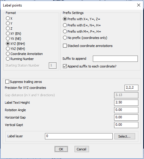
The GT_IDXYZ command labels picked points with X, Y, Z, XY or XYZ coordinate values. A number of formatting options can be specified as shown in the dialog above.
Watch: ![]()
Toolbar : Annotation Tools 
Menu : GeoTools -> Annotation -> Annotate points, based on layer names CmdLine : GT_ANNOTPOINTS
The GT_ANNOTPOINTS command is used to annotate a set of points based on a layer lookup table. This command is useful in several surveying applications where the raw data is first imported into AutoCAD / BricsCAD as a set of random point objects placed on several different layers. It is then often required to label these points with meaningful and descriptive text labels with correct text style and height. This command helps to create such a labeled text. Each set of annotation parameters (like text label, style, height etc) is specified on a per-layer basis. These sets of per-layer annotation parameters can be saved/restored from ASCII files.
Toolbar : Annotation Tools 
Menu : GeoTools -> Annotation -> Create / Update length annotation CmdLine : GT_LENTEXT
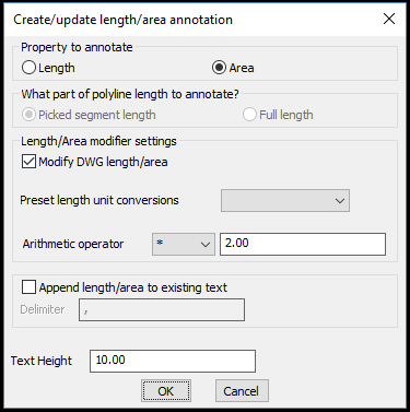
The GT_LENTEXT command creates a length or area annotation. If you have a line, polyline, arc, spline or a circle, its length (and area, where applicable for closed curves) can be easily annotated as text using this command. You can create .
The GT_LENTEXT command has been completely revamped and improved. In addition to length annotation, this command now supports area annotation also, which is also exposed through a new command alias called GT_AREATEXT.
The following improvements are made in the functioning of this command:
- For length annotations, you can now use arcs, circles and splines also, in addition to lines and polylines.
- For area annotations, you can use closed polylines, splines and circles.
- Area annotations from closed curves can be created as text objects, or existing ones updated (similar to CP_LENEXT functions).
- When existing text is updated with length or area values, you now have an option to append the value to the existing text. This feature was added based on user requests from many of our CAD detailing users who often want to capture a name and length/area quickly in DWG and export as CSV files to Excel. For example, a reinforcement detailing drawing containing the bar names and length, or bounded area names and area can now be easily tagged together in text objects (using the append option) and exported to Excel (via CSV) using the CP_TXT2FILE command easily. This significantly cuts down a painful and manual process of measuring each length using OSNAP and having to manually type it in along with the name into Excel. This enhancement is generic and is useful in a large number of CAD detailing situations in the quantity take-off department.
- The 'Modify length/area' and 'Pre-set length unit conversions' are fully supported for both length and area annotations.
- During length measurement of picked polylines, it is now possible to specify whether you want to annotate the full length of polyline or length of the picked segment alone. Earlier, the GT_LENTEXT command would only annotate the length of the picked segment and not the full length. With this optional setting, it is now easier for the users to have finer control of the output as desired.
- A number of other improvements have been made in the user interface and messaging for a better user experience.
Watch: ![]()
Toolbar : Annotation Tools 
Menu : GeoTools -> Annotation -> Create annotations at intersections CmdLine : GT_CREATEANNOT
The GT_CREATEANNOT command helps you create annotations across a line based on the intersecting objects along its path. The annotation is aligned perpendicular to the direction of the path and it can be either one of the following: Layer names/descriptions, Interval Distance or Cumulative Distance.
Watch: ![]()