Build Tools
 Toolbar : Build Tools
Menu : GeoTools -> Build -> Make rights-of-way / pavements / ramp  CmdLine : GT_ROWMAKER
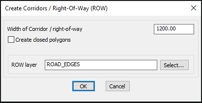
The GT_ROWMAKER command can be used to create right-of-ways by offsetting a road center line on both sides by a specified distance. It can be used with both 2D and 3D polylines, as well as polylines with arcs and Spline objects.
Width of right-of-way: Specify the width of the right-of-way.
Select R-O-W layer: Select the layer into which the newly created ROWs must be placed.Toolbar : Build Tools 
Menu : GeoTools -> Build -> Draw center from road R-O-W CmdLine : GT_CENTLINE
The GT_CENTLINE command is used to create road center lines from right-of-ways. The user must draw zig-zag lines across the right-of-way along its entire length. The mid-point of the segment of the zig-zag line that intersects the right-of-way is taken as the road center line point and the line joining a series of such center line points forms the road center line.
Command: GT_centline
Digitize Road Center Lines from Rights-Of-Way:
Pick Start point of line: <do so>
First zig-zag point: <do so>
Generate/Jump/Manual/Undo/eXit:<Next zig-zag point>: <pick a point or Type G, J, M, U or X>
....................
....................
....................
Upon starting the GT_CENTLINE command, you are asked to pick the start point of the road center line. Pick a point as shown in the illustration above. A sub-menu appears which provides the following options:
Generate/Jump/Manual/Undo/eXit <Next zig-zag point>:
The default option is to pick the next zig-zag point. In the illustration above, the zig-zag lines are shown by the red lines. GT_CENTLINE determines where each zig-zag line exactly intersects the right-of-way and calculates the mid-point between them as the road center line point.
Generate [G]: The Generate option is used to display the road centerlines drawn so far.
Jump [J]: The Jump option is used to temporarily suspend the digitization of a zig-zag point. This is an on/off toggle. This option is typically used when you want to skip certain areas and would like to move the zig-zag point to another place to continue the digitizing.
Manual [M]: The Manual option allows the road centerline points to be manually digitized. This option should be used when it is easier to specify the road center-line point by a direct pick rather than by the zig-zag method.
Undo [U]: The Undo option allows the last digitized centerline point to be undone.
eXit: The X option exits the GT_CENTLINE command and creates the road centerline digitized so far.Toolbar : Build Tools 
Menu : GeoTools -> Build -> Offset 3d polylines by distance CmdLine : GT_3DOFFSET
The GT_3DOFFSET command is used to offset 3d polylines in the same manner as 2d polylines. 3D polyline can be offset both horizontally and vertically. This can be a very useful in several civil engineering design situations that require the offsetted polyline to be offsetted and elevated or lowered by a fixed amount relative to the source polyline.
Menu: GeoTools -> Build -> Offset 3d polylines by distance
Switching to World Coordinate system...
Select 3d polyline to offset:
Horizontal Offset distance: <1.0000>: 25
Vertical Offset distance: <1.0000>: 2.5
Pick side to offset: Both/BOX/Layer/Xit <Xit>:b
Select 3d polyline to offset:
As you can see from the above transcript, there is an option to offset the 3d polyline in either the picked direction or on both sides or even create a closed box polyline out of the offsetted polyline. If you have a 2d polyline and want to offset using this command, simply change it to a 3d polyline first using the GT_CH2D3D command.
Watch: ![]()
Toolbar : Build Tools 
Menu : GeoTools -> Build -> Offset 3D polylines by Slope CmdLine : GT_3DOFFSETSLOPE
The GT_3DOFFSETSLOPE command is used to offset 3d polylines by providing a slope angle (either in degrees or in 1:n format) and a desired change in elevation. This is an extension of the existing GT_3DOFFSET command that does 3d offsets by horizontal and vertical distances only.
: GT_3DOFFSETSLOPE
Command added on: September 20, 2017
Menu: GeoTools -> Build -> Offset 3d polylines by slope
Switching to World Coordinate system...
Select 3d polyline to offset:
Enter slope in degrees (or enter slope in 1:n format) <45.0000>: 30
Enter desired change in elevation from original polyline <1.0000>: 2.5
Pick side to offset:
Toolbar : Build Tools 
Menu : GeoTools -> Build -> Offset 3D polylines along section CmdLine : GT_3DOFFSETSECTION
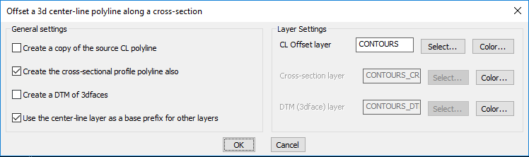
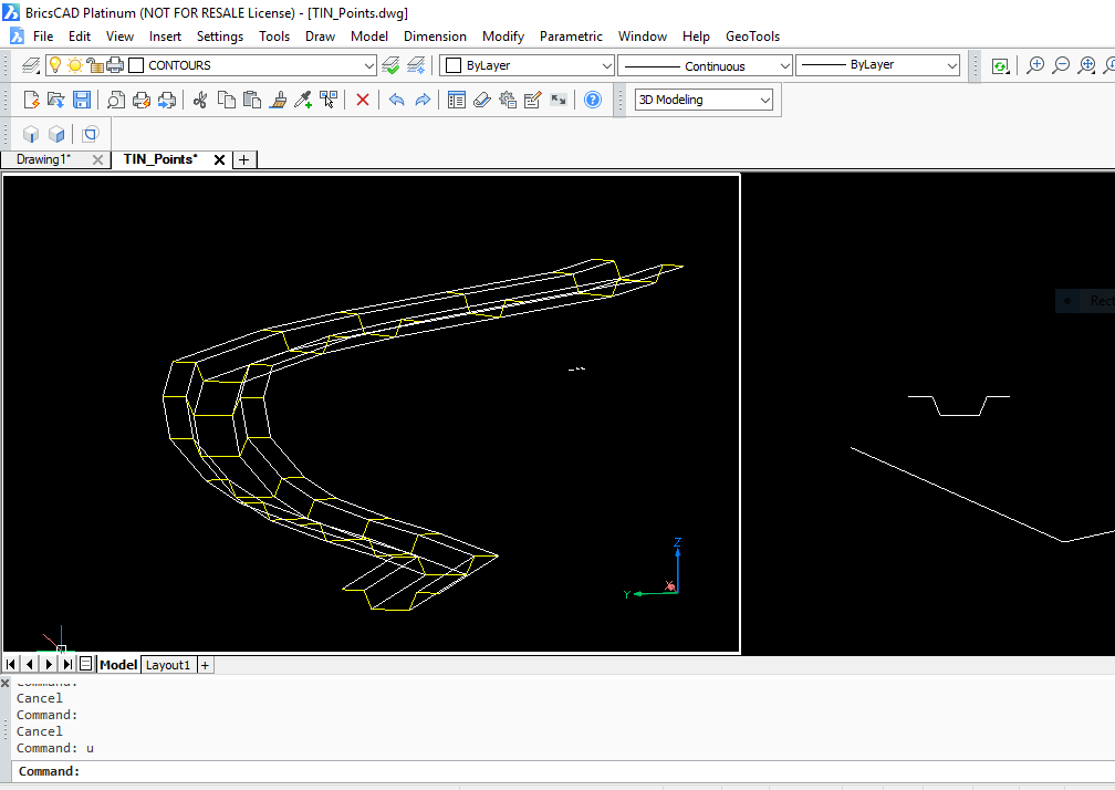
The GT_3DOFFSETSECTION command is used to offset a 3d (or even 2d) polyline along the defining points of a 2d cross-section, in such a way as to create a 3d model of the same. This is an extension of the existing GT_3DOFFSETSLOPE command that where only one side slope can be defined. The section option sweeps a 2d cross-section along a 3d (or 2d) polyline in such a way that a full 3d model is generated.
It is also possible to create a 3D DTM of the swept path surface using 3dface objects.
: GT_3DOFFSETSECTION
Command added on: September 20, 2017
Menu: GeoTools -> Build -> Offset 3d polylines along section
Switching to World Coordinate system...
Select 2d/3d polyline to use as center-line path:
Select 2d polyline to use as cross-section (CS) for offset:
Pick an anchor point on the CS polyline: <5405476.6187,5001190.3668,0.0000>:
Toolbar : Build Tools 
Menu : GeoTools -> Build -> Create centroid marks inside closed polygons CmdLine : GT_CREATECENTROID
The GT_CREATECENTROID command is used to create centroidal marks inside closed polylines, splines and circles.
Layer to create in:
Source: Creates the centroidal marks in the source layer( i.e the layer in which the closed polylines reside).
Current: Create all the centroidal marks in the current layer
Specify: Choosing this option allows specifying the layer in which the centroidal marks will be created.
Select: Clicking on Select button pops up the Select Layer dialog box.
Object to create: Specifies the type of object to create.
ACAD Point: An AutoCAD/BricsCAD point object is created at the centroidal location of each closed polyline.
Running Text Number: A Text string is created which is incremented by 1 each time for the next polygon being annotated with centroidal marks.
Fixed Text string: A fixed text string value is used for the annotation of the centroidal mark. The value of this text string is specified in the edit box provided for it.
Start Number: Specify the start number to be used for the annotation, if the Running Number Text option was chosen.
Format Width: Specify the required format width. This will prefix Zero before the running number text such that the string length is at least equal to the format width specified.
Fixed Text string value: Specify the value of the fixed text string to use for annotations.
Text Height: Enter the height for marking the Text string or Running number text.
Ensure that the centroidal point always falls physically inside polygon: If this option is checked and if the centroidal falls outside the polygon, it will be moved to a location physically inside the polygon.
The GT_CREATECENTROID command has an option to run without the dialog box selector. To enable this, you much check the option within the dialog box which says "Hide dialog box and run GT_CREATECENTROID in command-line mode next time". This setting is not saved in registry and reverts back to dialog box mode when your CAD is re-started.
Watch: ![]()
Toolbar : Build Tools 
Menu : GeoTools -> Build -> Multi-Variable Measure CmdLine : GT_MVMEASURE
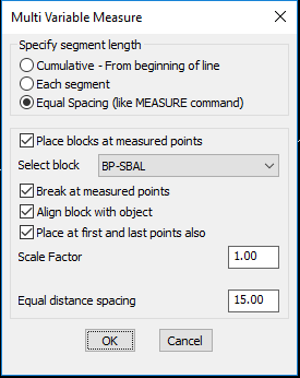
The GT_MVMEASURE command allows multiple and variable distances to be measured along lines, polylines and splines.
Specify segment length
Cumulative - From beginning of line: Select this option to mark the user specified distance on the polyline, always measured from the start of the polyline.
Each segment: Select this option to mark the user specified distance relative to and following (after) the previous segment.
Equal Spacing (like MEASURE command): Select this option to create points or blocks at equal spacing. This is similar to the standard MEASURE command, additionally it allows points to be placed at the start and end of the line, and also control the scale factor of the block being inserted.
Place blocks at measured points: This option allows you to select a block from the current drawing which will be placed at the measured point locations
Break at measured points: This option breaks the polyline at each of the measured positions.
Align block with object: Check this option to align the block with the slope of the line at each point.
Place at first and last point also: Checking this option automatically places a block or point at the first and last vertices of the curve.
Scale Factor: Specify the required scale factor for the block
A new option to place the blocks (or points) at equal spacing (like the MEASURE command) has been added. In addition to the MEASURE commands capabilities, this option also allows to specify the block scale factor and also place one at the start and end of the line too.
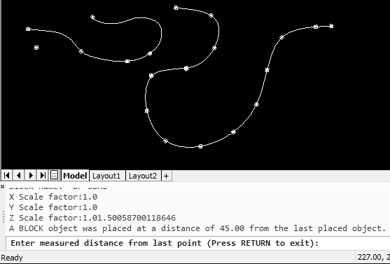
Better reporting of distances
We realized it is important to tell the user what exactly happened. So, we added new information messages during the run of the command which, now tells the user exactly at what distance from the start of the polyline (or from the last added point), a new object was created.
Toolbar : Build Tools 
Menu : GeoTools -> Build -> Join nearest ends of lines, polylines CmdLine : GT_JNE
The GT_JNE command is used to join the nearest ends of two selected lines and/or polylines with a connecting line and optionally join all the three into one single polyline.
Command: Select first object: (do so)
Select second object: (do so)
Join all segments together? [ Yes/No ] <Yes>:
Toolbar : Build Tools 
Menu : GeoTools -> Build -> Build common edges along closed, adjacent polygons CmdLine : GT_EDGEBUILDER
The GT_EDGEBUILDER command is a tool useful for building edges along adjacent, closed polylines. A typical scenario in GIS data preparation or modeling involves creating intersection-to-intersection edges on a network of closed polygons adjacent to each other. The GT_EDGEBUILDER command is an attempt to fulfill this need in an easy way.
Like in every GeoTools command, it is best to start with data that is as clean and accurate as possible. BEFORE you start this command, it is essential that all duplicate segments from the selection are removed and cleaned using the GT_DISTANGWEED command.
Toolbar : Build Tools 
Menu : GeoTools -> Build -> Build![]() Interpolate point elevation from neighboring polylines - manual pick CmdLine : GT_PTINTERMANUAL
Interpolate point elevation from neighboring polylines - manual pick CmdLine : GT_PTINTERMANUAL
The GT_PTINTERMANUAL command is useful to assign point elevations by interpolating the elevations of neighboring polylines.
Toolbar : Build Tools 
Menu : GeoTools -> Build -> Interpolate point elevation from neighboring polylines - automatic CmdLine : GT_PTINTERAUTOMATIC
The GT_PTINTERAUTOMATIC command is useful to assign point elevations by interpolating the elevations of neighboring polylines or 3dfaces from surface data. This is done by automatically scanning the surface data layers.
You are first asked for an initial zoom window size. If surface data for interpolation could not be found in the specified zoom, the value is incremented by 1.0 unit and a new search is initiated.
Next, you must specify the surface name to be used. A list of available saved surfaces are presented. The surface data must also be available in the drawing in the layer Surface<Surface_Name>. If such data is not available, it must first be imported using the GT_IMPORTSURFACE command.
Toolbar : Build Tools 
Menu : GeoTools -> Build -> Create closed polylines from a mass of networked polylines CmdLine : GT_CCPOLY
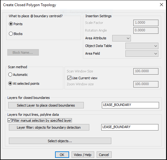
The GT_CCPOLY command is used to create closed polylines from a mass of inter-networked polylines, lines, arcs and circles. It is nothing but an automated version of the BPOLY command and it applies BPOLY at regular intervals in X and Y directions along a rectangular grid and creates closed polylines (resulting from BPOLY) from the adjoining boundary set. The program uses a parameter called 'Scan Window Size' to determine the BPOLY sampling interval. Needless to say, the GT_CCPOLY can be quite slow in its operation because it has no intelligent way to know how many unique closed polylines would be created. Since the BPOLY sampling is done at each regular interval, the program takes more time if the sampling interval is smaller and vice versa. Nevertheless, the program can be useful in many cases. Use it appropriately by specifying a scan window size that works with optimum speed and accuracy.
Scan method:
Automatic: Setting this option causes the command to scan at periodic intervals specified by Scan Window Size (see below) and a unique enclosing polygon created will be accepted as the output.This is a time consuming option and the Scan Window Size must be set judiciously after knowing your data pattern before-hand.
At selected points: This option is used if you already know your scan anchor points. Typically, these would be the centroidal locations or some such similar known points. The closed polygon generation is must faster when you know the points before-hand.
Scan Window Size: Enter the amount of search (scan) size. The selection set will be formed by searching around the scan point by a square window that is defined by this size.
Zoom Window size: Enter the amount of zoom size. While applying the scan window, the zoom is kept at this size. It is advisable to keep the zoom window slightly larger than the scan window for best results.
Select Layer for closed polylines : Clicking on this button pops up the dialog box for selecting the layers of closed polylines
Select Layer for polygon edges : Clicking on this button pops up the dialog box for selecting the layers of polygon edges.
Watch: ![]()
![]()
![]()
Toolbar : Build Tools ![]()
Menu : GeoTools -> Build -> Create a boundary (closed polygon) around a point CmdLine : GT_BOUNDARY
Description pending
Toolbar : Build Tools 
Menu : GeoTools -> Build -> Create mathematical offsets between two contour polylines CmdLine : GT_CONTOUROFFSET
The GT_CONTOUROFFSET command can be used to create an offset polyline in between two given contour polylines.
This command will ask the user for two polylines representing two contours and will create an intermediate "offset" polyline at the correct interpolated elevation between the two polylines.
The location of vertices for the offset polyline will be determined on the basis of configurable parameters like 'Offset Percent' (percentage distance between the two polylines) or an absolute distance from a point on the first polyline and measured towards a similar point on the second polyline.
The algorithm used to determine the offset polyline positions is not yet perfect to handle polylines of all geometric shapes. Often, the command may create offset polylines which are completely unacceptable as an interpolated offset. We would like you to be aware of these limitations.
To overcome some of these bugs, you may run the command again reversing the order of pick for the first and second polylines. This may sometimes produce better results.
Alternatively, you can also try to apply either of the two algorithms that the program uses. If one algorithm does not work for one set of polylines, the other might work or produce better results.
To determine a match point on the second polyline, the program uses a technique which is based on proportionally equivalent distance matching between and along the two polylines.
Algorithm to use:
Method 1: Select this option to use the primary algorithm
Method 2: Select this option to use the alternative algorithm, if the primary algorithm does not work.
Offset Method:
Percentage: If you select this option, the offset polyline will be created at the specified percentage distance between the first polyline and second polyline.
Distance: If you select this option, the offset polyline will be created at the specified distance from the first polyline towards the second polyline.
Sampling Method:
At Each vertex: The offset polyline created will have only as many vertices as the first source polyline.
At sampling interval: If you select this option, the first polyline will be sampled according to this interval and for each of these sampled points, the corresponding offset polyline points will be generated.
Sampling interval: Enter the distance along the first source polyline to create sampling points, which will then be used to create offset polyline points.
Percentage distance from first polyline: Enter the percentage distance from first polyline at which to create the offset polyline points.
Actual distance from first polyline: Enter the actual distance from first polyline at which to create the offset polyline points.
Toolbar : Build Tools 
Menu : GeoTools -> Build -> Place points along linear network CmdLine : GT_NETNODES
The GT_NETNODES command is used to place nodes (points) along a linear network of connected lines and/or polylines. This command performs a simple trace through the entire network and places points in such a way that that no two points are closer to each other than the specified distance which is measure along the network (and is NOT the straight line distance) between the two points. Please be aware that the command expects that the network is topologically correct, cleaned and that the end points of the lines are EXACTLY touching each other.
Distance interval for placing nodes : Specify the distance at which the nodes (points) have to marked.
Search window size : Specify the size for the search window as per the drawing unit.
Select layer to place nodes : Clicking on this button will pop-up the select layer dialog box for placing the nodes (points) in required layer.
Toolbar : Build Tools 
Menu : GeoTools -> Build -> Drape a 3D polyline across a set of intersecting linear objects CmdLine : GT_DRAPEPOLY
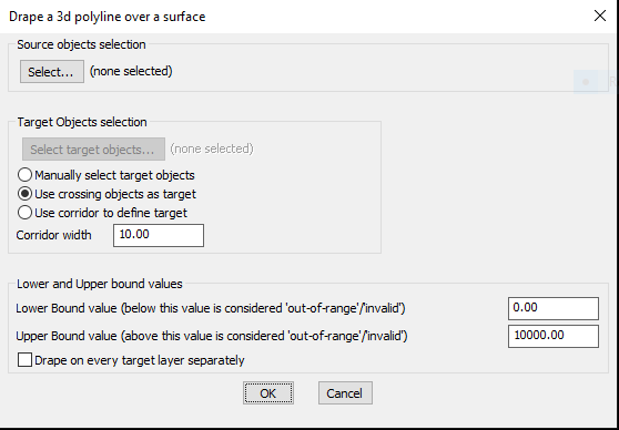
The GT_DRAPEPOLY command can be used to drape a set of 3d polylines (source objects) over a set of intersecting linear objects (target objects). Upon draping, this command creates vertices all along the source objects (3d polylines) where they intersect the target linear objects.
The dialog box above allows entry of various controlling parameters. You can specify 'Out-of-Range' values if you know the valid elevation limits of your data so that you can eliminate erroneous processing.
Selection of source objects is by a usual selection method. Selection of target objects can either be manual or by crossing or by a defined corridor.
For source objects, lines and polylines are the allowed selection objects.
For target objects, the acceptable objects for selection are lines, polylines, arcs, splines and 3dfaces.
Select source objects: (do so) - allows a filtered selection of 3d polylines only
Select target objects: (do so) - allows a filtered selection of linear objects like lines, polylines (both 2d and 3d), arcs and splines.
After GT_DRAPEPOLY runs, there will be new vertices created on the source polylines at every point where they intersect the target objects. If the intersecting objects are 3d, their 3d intersection value will be computed and used.
Watch: ![]()
Toolbar : Build Tools 
Menu : GeoTools -> Build -> Split larger polygons into smaller ones CmdLine : GT_POLYAREASPLIT
The GT_POLYAREASPLIT command is useful for those who want to proportion large closed polygons into smaller closed polygons cut to an exact target area. This is a useful tool in land acquisition and property parcel planning and sub-division activities.
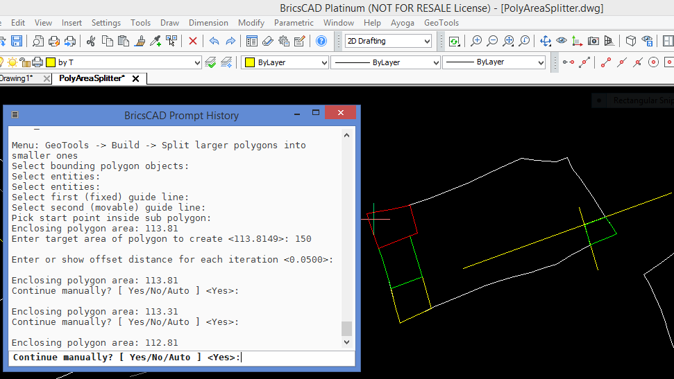
The GT_POLYAREASPLIT command mimics the manual process of trial & error to arrive at the closest area value. You first pick a closed polyline which represents the larger polygon that needs to be splitted. Next, you must provide two two guide lines, one stationary and another that is moved in small increments in a direction that increases the area. The entire process can be interactive or automatic. As soon as target area is reached, the program stops.
 Toolbar : Build Tools
 ![]()
Menu : GeoTools -> Build -> GeoTools Object Data -> Data Manager  CmdLine : GT_DATAMAN
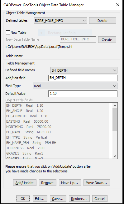
The GT_DATAMAN command is used to define a simple XDATA based database which operates entirely inside your CAD drawing. All data is stored in XDATA attached to entities and the database definition is provided in a simple INI file.
A sample structure of the INI file looks like this. Explanation about the syntax is provided after each section.
[*RECORD]
Name=BAR_INFO
Type=XDATA
FIELD=Section,String,1000
FIELD=Weight per unit length,Real,1000.0
FIELD=Cost per unit length,Real,500.0
FIELD=Supplier,String,Tata
FIELD=Photo,Link,(none)
[*RECORD_END]
The [*RECORD]....[*RECORD_END] section defines the database strcture. It is defined with lines having <Parameter>=<Value> syntax.
The 'Name' parameter specifies the database name (or the XDATA application name).
The 'Type' parameter indicates the type of database. In this case, it is 'XDATA'. In future, additional database types like 'ATTRIBUTES' etc will be introduced.
[*FIELD_VALUES]
Name=Section
Values=ISMB 200
Values=ISMB 300
Values=ISMC 400
[*FIELD_VALUES_END]
The [*FIELD_VALUES]....[*FIELD_VALUES_END] section defines the fields structure. This is also defined with <Parameter>=<Value> syntax.
The 'Name' parameter specifies the Field Name.
The 'Values' parameter defines the commonly used values for the field. These will appear in a pull-down menu when the GT_DATAMAN command is run.
There will be multiple [*FIELD_VALUES] section in the INI file, as many as the number of fields. However, it is not mandatory to define the [*FIELD_VALUES]. If this section is not defined for a field, there will be no pull-down menu options while entering data for the field.
The GT_DATAMAN command now supports an additional data type which allows files on the disk, server or cloud to be attached to selected objects. Using this option, you can create a link between an external file and your CAD entities. There is also a 'Show' option which allows to display the linked file automatically by launching the application with which it is associated.
For example, in the [RECORD] section above, the FIELD Photo is defined as a Link type. This means that it will offer Browse and Show buttons to select a file to be linked with the object and display it using the associated application.
 Toolbar : Build Tools
 ![]()
Menu : GeoTools -> Build -> GeoTools Object Data -> Attach Object Data  CmdLine : GT_ATTACHDATA
Description Pending
 Toolbar : Build Tools
 ![]()
Menu : GeoTools -> Build -> GeoTools Object Data -> Detach Data  CmdLine : GT_DETACHDATA
Description Pending
 Toolbar : Build Tools
 ![]()
Menu : CADPower -> Build -> CADPower Object Data -> Edit Data  CmdLine : GT_EDITDATA
Description Pending
 Toolbar : Build Tools
 ![]()
Menu : GeoTools -> Build -> GeoTools Object Data -> Copy Object Data  CmdLine : GT_COPYDATA
Description Pending
 Toolbar : Build Tools
 ![]()
Menu : GeoTools -> Build -> GeoTools Object Data -> Label CADPower Object Data  CmdLine : GT_LABELDATA
 Toolbar : Build Tools
 ![]()
Menu : GeoTools -> Build -> GeoTools Object Data -> Querry Object Data  CmdLine : GT_QUERYDATA
 Toolbar : Build Tools
 ![]()
Menu : GeoTools -> Build -> GeoTools Object Data -> Export CADPower Object Table Data to ASCII (CSV) files  CmdLine : GT_CPOD_EXPORT
Description Pending
 Toolbar : Build Tools
Menu : GeoTools -> Build -> GeoTools Object Data -> Import Object Data from CSV files CmdLine : GT_CPOD_IMPORT
Description Pending
 Toolbar : Build Tools
Menu : GeoTools -> Build -> GeoTools Object Data -> Create tabular CAD data from object table data  CmdLine : GT_CPOD_TABLEDATA
 Toolbar : Build Tools
 ![]()
Menu :GeoTools -> Build -> GeoTools Object Data -> Transfer block attributes to GeoTools object table data CmdLine : GT_CPOD_ATT2OD
Description Pending
.