Draw Tools
 Toolbar : Draw Tools
Menu : GeoTools -> Draw -> Enhanced, easy 3D point CmdLine : GT_EASY3DPOINT
GT_EASY3DPOINT allows 3d point objects to be created easily. It mimics the POINT command but allows the elevation value to be entered at each point pick prompt.
Toolbar : Draw Tools 
Menu : GeoTools -> Draw -> Draw embankment hatch slopes pattern CmdLine : GT_EMBHATCH
The GT_EMBHATCH command is use to draw a hatch pattern of alternating long and short lines of the kind shown in the figures below to represent an embankment slope pattern.
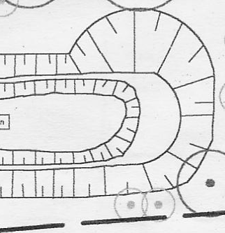
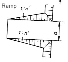
The GT_EMBHATCH command requires two boundaries represented as lines or polylines. The hatch pattern is created as a series of long and short lines with the specified spacing in between them. The ratio of the long and short lines is expressed as a percentage length. This command works on linear straight lines only.
The 'Hatch as 3d' option will additionally ask for elevations of the embankments and create the hatch lines in 3d. This helps in better visualization while annotating the terrain in a 3d context.
Watch: ![]()
Toolbar : Draw Tools 
Menu : GeoTools -> Draw -> Draw a polyline by joining points in sorted order CmdLine : GT_SORTEDPOLY
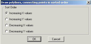
The GT_SORTEDPOLY command draws a polyline through selected points sorted in Positive X, Negative X, Positive Y or Negative Y direction.
Sort Order
Increasing X values : Choosing the option draws the polyline in increasing (positive) X direction.
Increasing Y values : Choosing the option draws the polyline in increasing (positive) Y direction.
Decreasing X values : Choosing the option draws the polyline in decreasing (negative) X direction.
Decreasing Y values : Choosing the option draws the polyline in decreasing (negative) Y direction.
Watch: ![]()
Toolbar : Draw Tools 
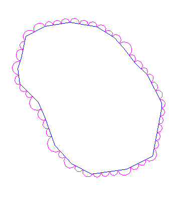
Menu : GeoTools -> Draw -> Create vegetation cover line pattern CmdLine : GT_VEGLINE
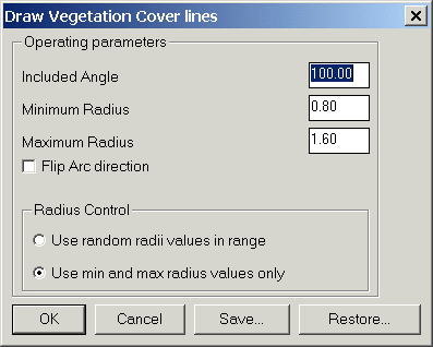
The GT_VEGLINE command is used to create vegetation cover line patterns. The patterns are drawn as arced polylines and you can control the size, shape and pattern of arcs as shown in the dialog box above. You can save and restore the parameters used by this command in ASCII files.
Layer to place Source: Explodes the polyline and places the result in the layer in which it was created (source layer)Current: Explodes the polyline and places the result in the layer which is currentSpecify: Explodes the polyline and places the result in the layer selected by the userLayer-name: Displays the name of the layer selectedSelect: Clicking on Select button pops up the select layer dialog boxDelete original objects: Checking this box deletes the original source object after exploding
Watch: ![]()
Toolbar : Draw Tools ![]()
Menu : GeoTools -> Draw -> Coordinates Table CmdLine : GT_CoordsTable
Description pending
Toolbar : Draw Tools ![]()
Menu : GeoTools -> Draw -> Parcel-Lots -> Draw Parcel-Lots CmdLine : GT_LOTMAKER
Description pending
Toolbar : Draw Tools ![]()
Menu : GeoTools -> Draw -> Parcel-Lots -> Parcel-Lots Labeling CmdLine : GT_LOTSLABELLER
Description pending
Toolbar : Draw Tools ![]()
Menu : GeoTools -> Draw -> Parcel-Lots -> Draw center-lines from guidelines CmdLine : GT_CLINE
Description pending
Toolbar : Draw Tools ![]()
Menu : GeoTools -> Draw -> Parcel-Lots -> Clean lot boundaries by snap/trim CmdLine : GT_EDGECLOSE