Drawing Cleanup Tools
 Toolbar : Drawing Cleanup Tools
Menu : GeoTools -> Drawing Cleanup -> Analyze and fix polyline elevation trends CmdLine : GT_ZTREND
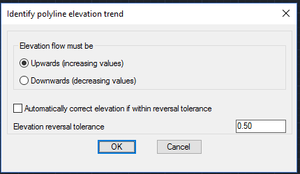
The GT_ZTREND command is used to analyze and fix (or set) Z elevation trends in 3d polylines.
In many 3d mapping situations, it is often necessary to ensure that digitized 3d polylines have consistently Upwards or Downwards flowing vertex elevations. The GT_ZTREND command helps to check and ensure this. In many instances of surveyed data, the elevation flow may temporarily be reversed within a tolerance. The command can also identify such within-tolerance reversals and fix the data
Elevation flow must be:
Upwards (increasing values): Checks if the polyline vertex is moving downwards consistently.
Downwards (decreasing values): Checks if the polyline vertex is moving downwards consistently.
Elevation reversal tolerance: Enter the tolerance within which the reversal should take place.
Include closed polylines also: Check this button to include processing of closed polylines also.
Automatically correct elevation if within tolerance: Checking this button causes the program to automatically correct polyline elevations when the variation is within tolerance.
The reporting structure in the GT_ZTREND command has been improved significantly. This command is used to determine the trend of elevation values in polyline vertices. The vertices where the elevation trend is not correct is highlighted by creating point objects at the locations in a temporary layer. The reporting structure has been improved considerably. At the end of the run, it now displays the full statistics of number of vertices with Z trend errors, found, fixed, ignored, as well as creates POINT objects in a temporary layer showing locations where the trend is not as desired. Additionally, an ASCII report file is also generated showing information from the processing.
Watch: ![]()
Toolbar : Drawing Cleanup Tools 
Menu : GeoTools -> Drawing Cleanup -> Remove Overlapping segments from lines selection CmdLine : GT_OVERLAP
The GT_OVERLAP command is a very powerful tool to quickly remove completely or partially overlapping line segments.
Toolbar : Drawing Cleanup Tools 
Menu : GeoTools -> Drawing Cleanup -> Delete duplicate entities CmdLine : GT_DELDUP
This command deletes duplicate entities from the current drawing. You can apply a linear tolerance value to determine how close the objects must be to be considered a duplicate. It is possible to further check if geometric duplicate entities have the same layer, Xdata, object data or Z value.
Toolbar : Drawing Cleanup Tools 
Menu : GeoTools -> Drawing Cleanup -> Linear and Node Snap (MAGNET) CmdLine : GT_NODELINESNAP
The GT_NODELINESNAP command is used to perform drawing cleanup of linear features and point features. This command fixes undershoot and overshoot errors in line feature data, by snapping points in linear objects to nearby linear or point features. Point feature data also can be cleaned by snapping them to other points or lines in the vicinity.
The ‘Snap Type’ section specifies which (source) feature type will snap to which other (target) feature type.
Linear features include AutoCAD / BricsCAD lines, polylines, arcs or spline objects.
Point or Node objects include AutoCAD / BricsCAD Point, Insert [Blocks] and Shape objects.
The command works equally well with both 2D and 3D objects. In case of a 3D object like a 3D polyline vertex, the snapping can be performed in either XY directions only retaining the existing elevation (Z) or it can snap in XYZ and inherit the elevation (Z) from the target object.
For snapping to linear objects, two tolerances, ENDpoint and NEArest are applied in that order around the point in question to search for the target point. The priority and values of these tolerances are of significance and must be set carefully after studying the data. First, the ENDpoint snap is applied and it that fails, the NEArest snap is applied next. Internally, the command uses the AutoCAD OSNAP function and these tolerances are based on OSNAP.
The ENDpoint and NEArest tolerances are applicable only when you are snapping to a linear object. The NODe tolerance is applicable when you are snapping to a point object.
The Z snap tolerance ensures that only source and target points whose elevation difference is lesser than this amount will only be snapped. This tolerance is provided to prevent points having a very high elevation difference from being snapped to each other.
Snap criteria for Line2Line / Line2Node: Additional snap criteria for Line2Line and Line2Node snap modes determine whether all vertices or only the end points will be considered for snap.
Snap Mode: (as explained above)
Snap to objects within current selection only: Checking this option causes the snap to be applied ONLY if the target point falls on an object which belongs to the initial selection and not to other objects in the drawing.
Snap options: This section provides options to mark and preview the points that would be snapped, or to snap automatically without preview.
Watch: ![]()
Toolbar : Drawing Cleanup Tools 
Menu : GeoTools -> Drawing Cleanup -> Identify intersecting segments (Kinks) in polyline CmdLine : GT_KINK
The GT_KINK command detects and highlights kinks in polylines. A kink is a "knot" or a "back twist”. A self intersecting polyline. The GT_KINK command helps identify these intersection points so that remedial action can be taken. The kink can then be removed with the Pedit or GeoTools Express Pedit command XV. The kink intersection is highlighted as point objects in a temporary layer.
Note: Polylines which have kinks will fail when used as selection boundaries in the ESELECT command.
Toolbar : Drawing Cleanup Tools 
Menu : GeoTools -> Drawing Cleanup -> Break crossing objects at ends CmdLine : GT_BREAKX
The GT_BREAKX command breaks polylines and lines located at the ends of selected lines and polylines. This command is often better than the equivalent tools in AutoCAD Map
Toolbar : Drawing Cleanup Tools 
Menu : GeoTools -> Drawing Cleanup -> Lineworks Intersection processor CmdLine : GT_INTEX
The GT_INTEX command is useful in processing a network of intersecting polylines. Using this command, polylines can be either broken (split) at their intersections or have a vertex added at the intersecting points. The command requires one or two selection sets of polylines to be defined - a source selection set and an optional target selection set. The source selection can be made to work on the target selection i.e. the source selection set objects look for intersections with the target selection set objects. Or, you can have the source selection set objects look for intersections with objects within itself.
The ‘Object Break’ and ‘Vertex Add’ operations can be applied either on the source, target or both selection sets.
Important note: The GT_INTEX command works only with polyline objects (both 2d as well as 3d). They must contain only linear segments and must not be splined, fitted or contain arc segments. If you have source objects that intersect with target objects that are 3d polylines, make sure that your source objects are defined as 3d polylines. If you have source objects that intersect with target objects that are 3d polylines, make sure that your source objects are defined as 3d polylines. Else, the interpolation will be incorrect.
The following related commands in GeoTools may be useful in preparing correct data for use by the GT_INTEX command.
Watch: ![]()
Toolbar : Drawing Cleanup Tools 
Menu : GeoTools -> Drawing Cleanup -> Detect free ends (dangles) of lines,polylines and arcs CmdLine : GT_DANGLECHECK
The GT_DANGLECHECK command is useful to detect free standing ends of polylines, lines, arcs and splines, also known as dangling ends. A user-defined search window tolerance is applied around the ends and if there is no other object in the vicinity, the end is treated as a free standing end or a dangle. All such end points are marked with POINT objects in the GeoTools temporary layer "GEOTOOLS_TEMP" so that they can be easily checked.
Search Window Size around endpoints: Enter the value for search window around the objects endpoints.
Toolbar : Drawing Cleanup Tools 
Menu : GeoTools -> Drawing Cleanup -> Create right angle corners CmdLine : GT_HSQUARE
The GT_HSQUARE command is a building squaring tool. It adjusts the angles of a polyline such that they form an exact right angle between adjacent segments. You can set an angle tolerance value to determine segments that should be adjusted. This tool is useful for fixing building edges (captured from satellite imagery) which are skewed because of camera or terrain tilt.
Watch: ![]()
Toolbar : Drawing Cleanup Tools 
Menu : GeoTools -> Drawing Cleanup -> Weed points based on spacing CmdLine : GT_POINTWEED
The GT_POINTWEED command removes points (or blocks) which are closer to each other by a user-specified distance.
Note: The precision value for search distance is set as per the current linear units precision
Toolbar : Drawing Cleanup Tools 
Menu : GeoTools -> Drawing Cleanup -> Check for coincident (XY) points with varying Z CmdLine : GT_ENDELEVCHECK
The GT_ENDELEVCHECK command is used to check the two end points of linear objects like lines, polylines, splines and arcs to see if there are other linear objects whose either end-point is at the same XY but different Z location. Optionally, a vertical line can be drawn connecting the two coincident points.
Toolbar : Drawing Cleanup Tools 
Menu :GeoTools -> Drawing Cleanup -> Set out-of-range elevation values to nearest valid elevation values CmdLine : GT_SET_Z_PL
Often, you may have polylines in which some vertices have a zero [0.0] elevation while others have non-zero elevations. The command GT_SET_Z_PL sets the Z values of those zero elevation vertices to the nearest non-zero vertex elevation value. The command scans through the polyline and seeks a non-zero value nearest to it and assigns it to the vertex. Thus, at the end of the command run, there will not be any polyline vertices, which are of 0.0 elevation. Therefore, this command is best used when you are sure that there should not be any vertex of elevation = 0.0 anywhere along the polyline.
Watch: ![]()
Toolbar : Drawing Cleanup Tools 
Menu : GeoTools -> Drawing Cleanup -> Make polylines/3dfaces planar CmdLine : GT_PLANARPOLY
The GT_PLANARPOLY command is used to make a polyline or 3dface planar. A planar polyline or 3dface is one in which all the vertices can be placed on a single plane. Generally, this is possible only if all the vertices have the same elevation or, in the special case of a 4-vertex polyline, the polyline can be considered planar if two pairs of adjacent vertices have the same elevation. The GT_PLANARPOLY command makes this happen by setting the elevations of adjacent vertices same if they are within a specified tolerance. The need to create perfectly planar polylines or 3dfaces is often required and useful in photogrammetry data capture and rendering applications.