Geographic Tools
 Toolbar : Geographic Tools
Menu : GeoTools -> Geographic Tools -> Coordinate Transform  CmdLine : GT_COORDTRAN
The GT_COORDTRAN command provides Coordinate Conversion from one system to another, It provides options to convert between the following coordinate systems:
- Lat-Longs (geographic)
- UTM (Universal Transverse Mercator)
- Transverse Mercator
- Lamberts Conformal Conic
- Albers Equal Area Projection
To use GT_COORDTRAN, you will need to know exactly what projection system your existing coordinates are in an what system you want it to be transformed to. You will also need to know which spheroid (and datum) your data should be in.
Toolbar : Geographic Tools 
Menu : GeoTools -> Geographic -> Coordinate Transform -> Setup CmdLine : GT_COORDTRAN_SETUP
The GT_COORDTRAN_SETUP command is used for setting the parameters for coordinate transformation. Please remember that the transformation parameters must be set with care and caution. If you are doing UTM2Geo or Geo2UTM transformation, you must specify the zone number correctly.
Toolbar : Geographic Tools 
Menu : GeoTools -> Geographic -> DWG2KML (Google Earth KML/Z Export) CmdLine : GT_DWG2KML
GT_DWG2KML is used to convert CAD data to Google KML files. The KML (Keyhole Markup Language) format is an ASCII (as well as binary [KMZ]) format in which vector data about geographic features on the surface of this earth can be represented. KML is a variant of the XML format and is the native format used by Google Earth and Google Maps to superimpose user-data on its maps. Vector data from CAD and other GIS software can be super-imposed on the satellite imagery in Google Earth providing a meaningful interpretation of the underlying terrain data. You can also attach attributes and terrestrial images (photos) to features which can be displayed on a popup window.
DWG2KML Main Dialog
DWG2KML Data setup Dialog
Watch: ![]()
Toolbar : Geographic Tools 
Menu : GeoTools -> Geographic -> KML2DWG (Google Earth KML/Z Import) CmdLine : GT_KML2DWG
The GT_KML2DWG command complements the GT_DWG2KML (Google Export) tool. In its first version now, the GT_KML2DWG command reads KML or KMZ files generated by Google Earth and recreates placemark points, polygons and paths in the drawing. The objects are placed in the drawing in the same units as those that exist in the KML/Z file. With this command, it is now possible to do a complete round-trip of information from CAD to Google Earth and back. The GT_DWG2KML command is used to export dwg entities to KML/Z format which can be opened in Google Earth.
Watch: ![]()
Toolbar : Geographic Tools ![]()
Menu : GeoTools -> Geographic -> DWG2KML-Batch Single Feature CmdLine : GT_DWG2KML_BATCH1F
The GT_DWG2KML_BATCH1F is a batch process, command-line version of the KML export program, which allows a single feature export.
Toolbar : Geographic Tools 
Menu : GeoTools -> Geographic Tools -> DWGKML-Batch Multiple Feature CmdLine : GT_DWG2KML_BATCHMULTF
GT_DWG2KML_BATCHMULTF allows multiple feature export in one operation, defined by schema and folder-based classification. This tool is suitable to be run in batch mode by supplying all the required parameters in a script file.
Toolbar : Geographic Tools 
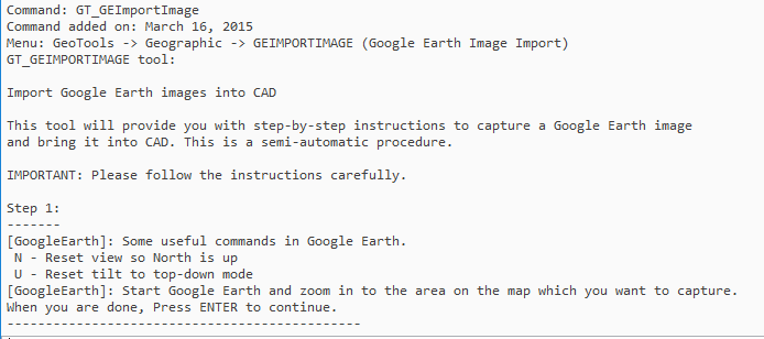
Menu : GeoTools -> Geographic -> GEIMPORTIMAGE (Google Earth Image Import) CmdLine : GT_GEIMPORTIMAGE
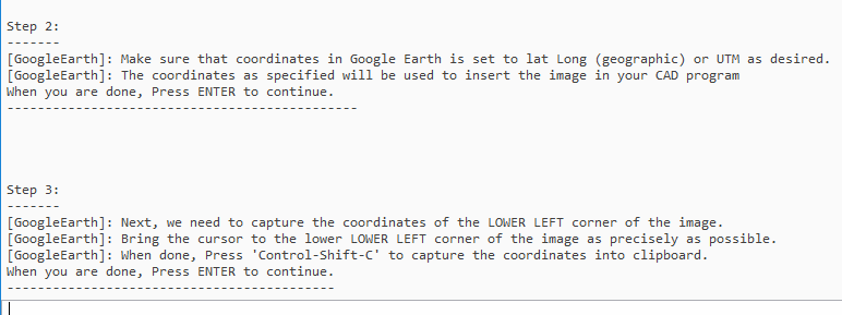
The GT_GEIMPORTIMAGE command is a process tool to capture a window view in Google Earth and import the same into CAD with geo-referenced coordinates. It is a semi-automatic, assisted procedure that involves using Google Earth commands & operations in an exact step-by-step procedure and attach the current Google Earth view in CAD using geo-referenced coordinates.
The accuracy of this procedure depends on the precision with which you capture the point coordinates and if all the instructions are followed as closely as possible.
The command relies on the ability of Google Earth to extract the cursor coordinates into clipboard memory using the Control-Shift-C command. You are asked to zoom to the area of interest and position the cursor at the lower left and upper right coordinates as accurately as you can. The coordinates are captured in clipboard using Control-Shift-C and accessed by CAD. You are then asked to save the image in Google Earth and the same is attached in CAD using the correct geo-referenced coordinates.
This is an approximate procedure but the results, if captured diligently, are pretty accurate for most checks and recce operations.
The GT_GEIMPORTIMAGE command has been significantly improved over several iterations, in the messaging and reporting departments. The importing of an image from Google Earth to your CAD platform is a fundamentally manual (or semi-automatic) process that involves several steps at the CAD level and at the Google Earth level.
The messaging and prompting of the instructions have been improved. As an illustration, we reproduce again the complete set of workflow that enables this tool to perform its task.
Toolbar : Geographic Tools ![]()
Menu : GeoTools -> Geographic -> GEIMPORTPOINT (Google Earth Point Import) CmdLine : GT_GEIMPORTPOINT
Description Pending
Toolbar : Geographic Tools 
Menu : GeoTools -> Geographic Tools -> Rubber Sheeting With Google Earth Control Points CmdLine : GT_GERSHEET
The GT_GERSHEET command is a quick way to do a 2-point rubber-sheeting of vector data from CAD to fit in Google Earth. The reference points for rubber-sheeting are defined from visually picked points on Google Earth and the same point is to be picked in the CAD drawing also. The GT_GERSHEET command uses the coordinates information from Gogle Earth and maps it to the drawing coordinates and stretches (rubber-sheet) the data in the CAD to match the Lat-Long coordinates of Google Earth. It works on the same principle of as GT_GEIMPORTIMAGE which is used to import geo-referenced screen-shots from Google Earth into CAD.
The GT_GERSHEET rubber-sheets and fits your existing CAD data into the LatLong format as expected by Google Earth. The command works by asking to pick two known points in CAD and in Google Earth. With these coordinates, a simple rubber sheeting (scale and move) is performed.
This ensures that the coordinates are now in Lat Long coordinates matching Google Earth coordinates.
The command provides step-by-step instructions on how to setup and capture your coordinate both in CAD and in Google Earth.
First, you pick the first known point in your CAD data and zoom into the same location in Google Earth. You then capture the LatLong coordinates of the point in Google Earth using Control-Shift-C. These coordinates are transferred to CAD from the clip-board.
Next, you pick the second known point in CAD and zoom into the same location in Google Earth. Capture the coordinates again using Control-Shift-C and the coordinates are transferred to CAD again.
Using these two pairs of known source & target coordinates, GeoTools does a simple scaling and moving to fit the selected CAD data into the correct geographical location as required by Google Earth.
The GT_GERSHEET command requires you to have your CAD and Google Earth running together to perform its job.
Next, you can export this data to Google Earth using the GT_DWG2KML command, and the KML file is imported into Google Earth to fit the imagery exactly.
Watch: ![]()
Toolbar : Geographic Tools 
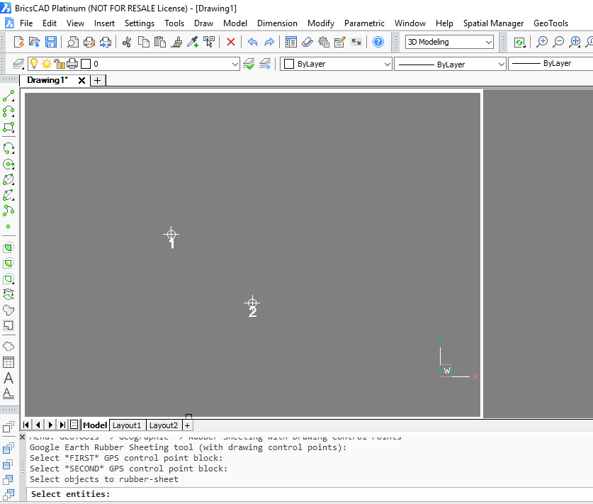
Menu : GeoTools -> Geographic -> Rubber Sheeting with Drawing Control Points CmdLine : GT_GERSHEETWITHCTRLPOINTS
The GT_GERSHEETWITHCTRLPOINTS command is another quick way to do a 2-point rubber-sheeting of vector data from CAD to fit in Google Earth. The GT_GERSHEETWITHCTRLPOINTS command complements the GT_GERSHEET command. This command requires two pre-existing control points in the drawing (defined as block named GT_GPS_POINT) and they are used to rubber-sheet and fit the data from Lat-Long coordinates to UTM or vice-versa.The reference points for rubber-sheeting are defined from visually picked points on Google Earth and the same point is to be picked in the CAD drawing also.
Toolbar : Geographic Tools ![]()
Menu : GeoTools -> Geographic Tools -> Import elevations from Google Earth CmdLine : GT_GEIMPORTELEVATIONS
Description Pending
Toolbar : Geographic Tools 
Menu : GeoTools -> Geographic Tools -> Insert a geo tagged photo CmdLine : GT_INSPHOTO
GT_INSPHOTO allows a geo-tagged photo to be attached to your CAD drawing. Geo-Tagging is a method by which geographical position info is attached to a normal photo image (JPG, PNG, GIF etc) as a meta data, such that the location (latitude and longitude) where the photo was taken is stored along with the image file. Such a capability is now common-place with smart phones and tablets which have built-in GPS capabilities. It is also possible to geo-tag a photograph using many of the higher end cameras in the market today.
The GT_INSPHOTO is a great tool to import your geo-tagged images into CAD for subsequent export into a KML file using the GT_DWG2KML command.
You can select multiple image files for import, a starting ID, an ID prefix and also determine the next highest available ID in your drawing. The EXIF data from the images can also be saved optionally as xdata attached to the objects so that they can be further exported into a KML file is necessary or used by other programs, or using the GT_DWG2KML function in GeoTools.