Miscellaneous Tools
 Toolbar : Miscellaneous Tools
Menu : GeoTools -> Miscellaneous -> Images -> Insert GEO-Referenced images  CmdLine : GT_GEO_INS
The GT_GEO_INS command can be used to insert geo-referenced image files. These image files can be either in the TIF, BMP or JPG format and they MUST be accompanied by their world files as well. The World files have an extension of TFW, BPW or JGW respectively. This command DOES NOT import GeoTIFF files in which the geo-referencing information is stored in the file header.
Toolbar : Miscellaneous Tools 
Menu : GeoTools -> Miscellaneous -> Images -> Scan selected image files and build image boundary list CmdLine : GT_IMAGESCAN
The GT_IMAGESCAN command is a pre-processor command which scans multiple image files and their corresponding world files and builds an in-memory list of image-name and their positioning information (insertion point, extents etc) which will be used by the next command, GT_IMAGESEARCH.
The following image formats are supported: tif, jpg, bmp and png. Their corresponding world files must have the extension tfw, jpw, bmw and pgw respectively.
Toolbar : Miscellaneous Tools 
Menu : GeoTools -> Miscellaneous -> Images -> Insert geo-referenced image corresponding to selected AOI CmdLine : GT_IMAGESEARCH
GT_IMAGESEARCH asks the user to specify an area of interest (rectangular boundary) and will search the scanned images in memory (created using the GT_IMAGESCAN command) and attach the image corresponding to the specified Area of interest.
Toolbar : Miscellaneous Tools 
Menu : GeoTools -> Miscellaneous -> Roughen a Line CmdLine : GT_ROUGHEN
Pick a linear object (line or polyline) and roughen it. The roughened line contains randomly created zig-zags on either side of the center line
Toolbar : Miscellaneous Tools 
Menu : GeoTools -> Miscellaneous -> Compute surface area of 3DFaces CmdLine : GT_SURFAREA
Computes the surface area as well as horizontally projected area of selected 3DFACE objects. In addition, you have the option to create the 'projected' 3DFACE objects on the XY plane.
Toolbar : Miscellaneous Tools ![]()
Menu : GeoTools -> Miscellaneous -> Explode objects - Retain Object Table and extended entity data CmdLine : GT_XP_RETDAT
Description Pending
Toolbar : Miscellaneous Tools 
Menu : GeoTools -> Miscellaneous -> Report on areas covered by HATCH objects CmdLine : GT_HATCHAREA
The GT_HATCHAREA command produces a report of selected hatch objects. It shows the area covered by each class of hatch pattern as well as number of hatch objects in each pattern, and additional information about solid/gradient hatches, color tones etc.
Toolbar : Miscellaneous Tools 
Menu : GeoTools -> Miscellaneous -> Break(Split) objects along a polyline CmdLine : GT_CONTBREAK
The GT_CONTBREAK command is a general purpose command to break a drawing along a boundary. The boundary can be open or closed and must be defined as a polyline.
In the above illustration, you see a screenshot of a very dense contour drawing. By setting up appropriate closed polyline cutting edges (blue lines in the figure above), it is possible to break the contours easily at the boundary of these polygons. Once broken, each part can be exported into it own DWG using the GeoTools GT_ESELECT and the WBLOCK command.
Toolbar : Miscellaneous Tools 
Menu : GeoTools -> Miscellaneous -> Enter the co-ordinates of point in geographic format [Lat-Long] CmdLine : GT_GEO
GT_GEO is not a GeoTools command that can be run off the command line. Instead, it is a transparent function which can be called at any point when AutoCAD / BricsCAD is expecting a point input. The (geo) function helps to input coordinates in geographic coordinates (Latitudes and Longitudes) in degree-minute-second format (for example, 33° 01' 53.8739",18° 01' 11.2246",480.0 is a Latitude of 33° 01' 53.8739" and a Longitude of 18° 01' 11.2246" and a height of 480.0
Note: 1) You have to run (GEO) function by typing in PARENTHESES without which it will not run.
2) The (geo) function can be called ONLY when an AutoCAD / BricsCAD command (and not a GeoTools command) is expecting for a point entry.
Toolbar : Miscellaneous Tools ![]()
Menu : GeoTools -> Civil -> Create contour area table CmdLine : GT_CONTAREATABLE
Toolbar : Miscellaneous Tools 
Menu : GeoTools -> Miscellaneous -> Classify Elevation Contours CmdLine : GT_CONTCLASS
This command places objects representing contours (polylines or LDDT contour objects) into different layers according to their contour interval.
You can select a maximum of five contour intervals and specify a layer name for each of these contour intervals. The selected contour objects are then placed in their allotted layers. You can select polyline objects or LDDT contour objects.
Tip: GT_CONTCLASS can be used as a terrain analysis tool or for creating map output showing contours of specific elevations only.
Toolbar : Miscellaneous Tools 
Menu : GeoTools -> Miscellaneous -> Delete paper-space layouts CmdLine : GT_DELETELAYOUTS
The GT_DELETELAYOUTS command will present you with a list of all paper space layouts and you can select multiple layouts and delete them in one go.
Toolbar : Miscellaneous Tools 
Menu : GeoTools -> Miscellaneous -> Contour spacing distance tool CmdLine : GT_CONTDIST
The GT_CONTDIST command is an intra-contour spacing checker and contour breaking tool. Often, when the distance or spacing between two adjacent contours is too small, it is difficult to either view the contours clearly or to create un-cluttered labels to depict the contours. In such situations, it is useful to break the contours at locations where the distance between the contour and the adjacent contours on either side is less than a specified Distance Tolerance.
The GT_CONTDIST command measures from each vertex of the contour polyline, the distance on either sides of the contour being processed, and if the distance is less then the specified Distance Tolerance then that point is marked in memory for breaking. In this manner, the whole contour polyline is checked and the segments that are within the Tolerance distance from the adjacent contours are broken.
The contours can be checked for proximity at each vertex or at a fixed regular interval along its length.
Exclude major / special contours from breaking: Checking this box allows to exclude major contours and specified exclusion contour elevations from breaking.
Toolbar : Miscellaneous Tools 
Menu : GeoTools -> Miscellaneous -> CSV Editor CmdLine : GT_CSVEDITOR
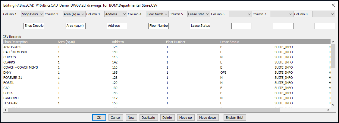
GT_CSVEDITOR is used to edit comma delimited ASCII text files within the CAD editor. The current version allows to edit CSV files with a max. 8 columns of CSV data. The data is presented in a dialog box and each column can be edited by entering a new value in the edit box or choosing one from the pull-down menu. A pre-defined set of probable values can be defined and supplied to the command.